
What Size Wire for 60 Gallon Air Compressor Practical Guide for 2026
Determine what size wire for 60 gallon air compressor requirements in October 2026 with accurate wire gauge calculations, breaker sizing rules, and workshop safety tips.
 By Bob Beacham
Updated October 8, 2026
By Bob Beacham
Updated October 8, 2026

Stationary workshop air compressors demand substantial electrical power to compress high volumes of air without stalling or overheating. Determining what size wire for 60 gallon air compressor installations require depends primarily on the continuous running amperage of the electric motor rather than the physical capacity of the steel tank alone. A typical 60-gallon stationary compressor utilizes a 230-volt single-phase electric motor ranging from 3 horsepower to 7.5 horsepower, each presenting distinct branch circuit demands. Sizing the electrical conductor incorrectly can lead to severe voltage drops, nuisance breaker trips, and accelerated motor winding degradation.
Selecting the correct wire gauge requires evaluating the motor full load amperes, breaker specifications, and the total distance between the breaker panel and the compressor location. Heavy-duty units, including the VEVOR 60 Gallons Heavy-Duty Air Compressor, draw significant inrush current during cold startups against pressurized head lines. Integrating robust components such as a Square D Pumptrol Pressure switch for compressed systems ensures reliable automated motor cycling while maintaining circuit integrity. This practical guide examines exact electrical conductor requirements, National Electrical Code recommendations, and workshop installation safety.
| Award | Product | ACR Score About ACR ScoreThe ACR Score is our own rating from 0 to 10, based on performance, design and build, ease of use, and value. It reflects independent research and is never influenced by manufacturers, retailers, or affiliate commissions. Learn more › | |
|---|---|---|---|
| Best Overall |
VEVOR 7.5HP Air Compressor Electric Motor
|
9.2/10 | Buy |
| Best Premium |
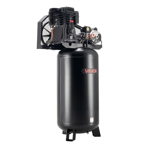 VEVOR 60 Gallons Heavy-Duty Air Compressor
|
8.9/10 | Buy |
| Best Budget |
 VEVOR 3HP Air Compressor Electric Motor
|
8.1/10 | Buy |
 Square D 9013FHG12J52M1X 95-125 PSI Switch
|
7.8/10 | Buy | |
| Best Value |
 VEVOR 5HP SPL Air Compressor Electric Motor 230V
|
7.8/10 | Buy |
Square D 9013FHG12J52M1X 95-125 PSI Switch
Designed for air compressor systems, the Square D 9013FHG12J52M1X maintains operating levels between 95 and 125 psi. It incorporates an unloader valve and a dedicated on-off lever for reliable compressor cycling and manual control.
Pros
- Factory-calibrated 95 to 125 psi operation
- Built-in unloader valve prevents hard compressor starts
- Dedicated on-off lever allows easy manual shutdown
- Compact and lightweight footprint
Cons
- Single-port design limits direct accessory mounting
- Specific pressure range requires adjustment for custom PSI needs
Complete Electrical Wire Sizing Guide for 60-Gallon Air Compressors
Selecting the correct conductor size for a stationary workshop air compressor requires understanding the relationship between electric motor draw, circuit protection, and supply voltage. A 60-gallon air compressor stores a substantial volume of pressurized air, but the electrical demand originates entirely from the electric motor mounted to the pump head. Wiring an installation with undersized conductors creates high electrical resistance, resulting in dangerous heat generation, severe voltage drop, and sluggish motor startup. Evaluating the specific nameplate ratings of your compressor ensures reliable operation while complying with standard electrical codes.
Determining Wire Gauge Based on Compressor Motor Horsepower and Amperage
Tank capacity indicates air storage volume rather than electrical current consumption. A 60-gallon receiver tank may be paired with a 3 horsepower motor, a 5 horsepower motor, or an industrial 7.5 horsepower motor depending on pump configuration and required air delivery. Because these stationary units run on 230-volt single-phase power, each horsepower tier demands a specific American Wire Gauge (AWG) conductor size to operate safely. Sizing wiring strictly by tank capacity without verifying motor electrical specifications remains a common and risky error.
A 3 horsepower electric motor drawing approximately 15 amperes to 17 amperes under full load typically requires 10 AWG copper conductors for short workshop runs. For a 5 horsepower motor drawing between 17 amperes and 24 amperes, 8 AWG copper wire represents the standard requirement to handle sustained current flow. High-output 7.5 horsepower electric motors, such as the VEVOR 7.5HP Air Compressor Electric Motor, draw roughly 31.6 full load amperes and mandate 6 AWG copper conductors on a dedicated branch circuit.
Single-stage and two-stage pump designs create different load profiles for the electric motor during pressure build. Two-stage pumps compress air to higher final pressures, often reaching 175 PSI, which forces the motor to draw its full rated amperage during the final stage of the fill cycle. Single-stage units, like the VEVOR 60 Gallons Heavy-Duty Air Compressor operating up to 145 PSI, maintain steady torque requirements across the cycle. Identifying whether your pump operates in a single or dual stage configuration reinforces the need for properly sized copper conductors.
Understanding Full Load Amps and Continuous Duty Circuit Rules
Full Load Amps (FLA) defines the steady-state electrical current the motor draws when delivering its rated horsepower under maximum tank pressure. Nameplate FLA serves as the baseline calculation metric for determining branch circuit conductor sizing and upstream circuit breaker capacity. Electric motors powering workshop compressors encounter increasing mechanical resistance as tank pressure climbs toward the factory cut-out threshold. Designing an electrical feed based on idle or unloaded motor amperage will quickly result in overloaded conductors.
The National Electrical Code mandates that branch circuit conductors feeding stationary electric motors must carry at least 125 percent of the motor rated full load current. This safety margin accounts for the continuous duty thermal strain placed on electrical wiring during extended recovery cycles. For example, a motor rated at 17.6 FLA requires conductors with an allowable ampacity of at least 22 amperes after applying the 125 percent multiplier. This rule prevents conductors from reaching elevated temperatures inside walls or conduits during long air tool usage sessions.
Discrepancies between advertised peak horsepower and continuous running horsepower complicate electrical planning for many workshop owners. Retail marketing often highlights peak surge horsepower, labeling units as 5 HP SPL when continuous running output aligns closer to 3.5 horsepower. The VEVOR 5HP SPL Air Compressor Electric Motor 230V lists an FLA of 17.6 amperes, reflecting this specific design classification. True industrial continuous 5 horsepower motors draw closer to 22 to 24 amperes, requiring heavier 8 AWG copper wire rather than 10 AWG conductors.
Circuit Breaker Sizing Versus Wire Ampacity for Compressor Motors
Stationary air compressor motors require significant electrical energy to initiate rotation from a dead stop against mechanical friction and line pressure. This startup inrush current frequently reaches five to seven times the continuous running amperage for a brief fraction of a second. Standard residential circuit breakers designed for domestic branch circuits can trip instantaneously during this initial current spike. Dedicated motor circuits accommodate this surge by utilizing breakers specifically sized for motor starting demands.
Equipment manufacturers frequently specify circuit breaker sizes that appear larger than the continuous ampacity rating of the wire. For example, the VEVOR 3HP Air Compressor Electric Motor carries a manufacturer recommendation for a 40-amp circuit breaker, while the continuous wire sizing requires 10 AWG or 8 AWG copper. Similarly, the VEVOR 7.5HP Air Compressor Electric Motor recommends a 60-amp circuit breaker to tolerate its high startup spike. These recommendations reflect branch circuit short-circuit protection rules rather than continuous overcurrent thresholds.
Electrical safety codes permit sizing the circuit breaker higher than conductor ampacity for dedicated motor circuits because the motor features its own thermal overload protection. The upstream circuit breaker primarily shields the circuit against ground faults and dead short circuits. The thermal overload reset mechanism mounted on the motor housing protects the wire and motor windings from prolonged overheating caused by mechanical pump binding. Both protection elements work together to ensure reliable operation without nuisance tripping.
Calculating Voltage Drop Across Garage and Workshop Wire Runs
Electrical current flowing through copper conductors encounters natural internal resistance that dissipates voltage over extended linear distances. When a stationary 60-gallon compressor is located in a detached garage, barn, or opposite workshop corner, the linear wire run can easily exceed 50 to 100 feet. Excessive distance diminishes the voltage available at the compressor terminals, which impairs motor torque and increases current draw. Calculating total line distance represents a vital step before purchasing wiring materials.
National electrical standards recommend keeping voltage drop below 3 percent under full rated load to maintain optimal motor efficiency. On a standard 230-volt single-phase supply, a 3 percent drop corresponds to a maximum allowable loss of 6.9 volts, ensuring the motor receives at least 223 volts at the terminals. Operating a heavy-duty compressor below this voltage threshold forces the motor to run hotter, slows down recovery times, and risks triggering internal thermal overloads during warm weather.
Compensating for distance requires upsizing the conductor gauge beyond baseline ampacity requirements. An installation requiring 8 AWG copper for a 5 horsepower motor at 30 feet should be upgraded to 6 AWG copper if the run extends past 75 feet. For a 7.5 horsepower motor drawing over 31 amperes, distances exceeding 60 feet justify stepping up from 6 AWG copper to 4 AWG copper. Investing in heavier wire preserves operating voltage and extends the functional lifespan of the compressor motor.
Comparing Copper Conductor Types and Conduit Requirements
Copper conductors remain the preferred standard for stationary air compressor wiring due to their superior electrical conductivity and mechanical stability. While aluminum wire offers lower material expense, it exhibits higher electrical resistance, requiring larger physical wire gauges to carry equivalent amperage. Aluminum connections also expand and contract significantly under cyclic thermal loading, which can loosen terminal connections under continuous compressor vibration. Copper wire ensures tighter terminations and long-term reliability.
Selecting between non-metallic sheathed cable and individual insulated conductors depends on your workshop installation pathway. NM-B Romex cable is commonly used inside finished residential wall cavities, but code restricts its ampacity calculations to the 60-degree Celsius column. Individual THHN or THWN conductors installed within conduit are rated for 75-degree or 90-degree Celsius applications, permitting higher allowable current within smaller physical diameters. THHN wire inside conduit provides superior thermal dissipation for heavy workshop tools.
Physical conduit protection is essential in busy garage and workshop environments where moving vehicles, hand tools, and sparks pose hazards. Running electrical metallic tubing (EMT) or rigid PVC conduit along workshop walls shields the conductors from accidental impact or abrasion. Rigid conduit also provides a solid structural pathway that neatly houses individual THHN conductors, establishing a clean and professional workshop utility layout.
Wiring the Pressure Switch and Unloader Valve for Safe Cycling
The pressure switch acts as the automated electrical controller that monitors tank pressure and switches electrical current to the motor. Components like the Square D Pumptrol Pressure switch for compressed air systems feature heavy-duty contacts rated for industrial cycle counts. On a 230-volt single-phase installation, the pressure switch uses a double-pole mechanism that disconnects both incoming hot power conductors simultaneously when the cut-out setpoint is reached.
Coordinated pressure management relies on an integrated unloader valve to relieve residual air trapped between the compressor pump head and the check valve. When the pressure switch contacts snap open at the maximum tank pressure, the unloader lever opens a small mechanical exhaust port. Bleeding this trapped air allows the electric motor to restart with zero head resistance during the next cut-in cycle. Proper wiring alignment inside the switch enclosure must never interfere with the physical movement of the unloader arm.
Terminating large 8 AWG or 6 AWG conductors inside a compact pressure switch enclosure demands careful mechanical handling. Heavy copper strands must be stripped cleanly without nicking the metal and tightened securely beneath the terminal clamping plates according to manufacturer torque specifications. Loose terminal screws create electrical resistance, generating localized heat that can scorch switch contacts and cause premature switch failure.
Safe Installation Sequence, Disconnect Switches, and Vibration Control
Thorough planning begins with an evaluation of your main electrical service panel to confirm adequate electrical service headroom. Installing a dedicated 230-volt compressor circuit requires two open vertical breaker slots to accommodate a dedicated double-pole circuit breaker. Never attempt to power a stationary 60-gallon compressor by tapping into existing general-purpose 120-volt convenience circuits or shared 240-volt appliance lines. Dedicated circuits prevent dangerous multi-tool overloads.
Installing a manual safety disconnect switch adjacent to the compressor provides a critical layer of workshop safety. Electrical codes typically require an accessible disconnecting switch within sight of stationary motorized equipment exceeding 2 horsepower. A wall-mounted, enclosed 60-amp disconnect switch allows operators to cut electrical power instantly before performing belt inspections, pump oil changes, or air filter replacements without walking across the workshop to the main breaker panel.
Vibrations produced by heavy-duty reciprocating pumps can loosen rigid conduit connections if mechanical isolation is not provided. Running rigid EMT conduit to a wall-mounted junction box and completing the final connection to the compressor with flexible metallic conduit isolates motor vibration. Securing this flexible whip with proper strain relief connectors protects the electrical wiring terminals from continuous vibration fatigue, ensuring reliable electrical delivery over the life of your equipment.
About the author
Bob Beacham is an experienced tools and workshop writer with deep knowledge of power equipment, mechanical systems, and practical DIY applications. His coverage of air compressors, welding equipment, saws, and workshop tools helps translate technical specifications into useful guidance for homeowners and serious DIYers.