
How to Hook up Extra Tank to Air Compressor: A Practical Guide for 2026
Learn how to hook up extra tank to air compressor in October 2026. Expand reserve storage, stop line pressure drops, and set up auxiliary tanks safely.
 By Kenny Koehler
Updated October 8, 2026
By Kenny Koehler
Updated October 8, 2026
High-demand pneumatic tools like dual-action sanders, high-torque impact wrenches, and paint sprayers can quickly drain small air compressor reservoirs. When a pump continuously cycles and line pressure plummets below ninety PSI, work grinds to an abrupt halt. Learning how to hook up extra tank to air compressor setups gives your pneumatic system a larger buffer of pressurized air, preventing rapid pressure drops during brief, heavy tool use. Adding an auxiliary air tank stores more potential energy so your tools maintain peak torque and consistent airflow for longer stretches.
While adding a secondary vessel doubles your stored gallon capacity, it does not magically increase the compressor pump’s true continuous output rating in cubic feet per minute. Plumbing an auxiliary tank requires careful attention to pressure switch placement, pipe thread sealing, pressure vessel safety relief limits, and daily moisture drainage. Setting up this configuration properly ensures you get extended pneumatic runtime without overheating the electric motor or creating dangerous pressure hazards in your garage workshop.
| Award | Product | ACR Score About ACR ScoreThe ACR Score is our own rating from 0 to 10, based on performance, design and build, ease of use, and value. It reflects independent research and is never influenced by manufacturers, retailers, or affiliate commissions. Learn more › | |
|---|---|---|---|
| Best Overall |
SUNROAD 2-Pack Extended Air Compressor Tank Drain
|
9.1/10 | Buy |
| Best Premium |
 QWORK 2-Pack Air Compressor Extended Tank Drain
|
9.1/10 | Buy |
| Best Value |
 Hromee 5-Piece 1/4-Inch Drain Valve Kit
|
8.9/10 | Buy |
 Hromee Automatic Air Compressor Tank Drain Valve
|
8.6/10 | Buy | |
| Best Budget |
 Hromee Air Tank Manifold Replacement with Fill
|
8.4/10 | Buy |
 SUNROAD 10-Inch Compressor Tank Drain Kit
|
8.3/10 | Buy |
SUNROAD 2-Pack Extended Air Compressor Tank Drain
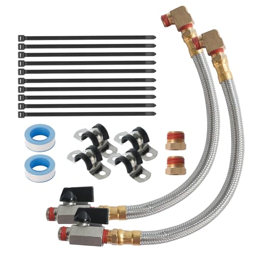
The SUNROAD 2-Pack Extended Tank Drain Valve Kit relocates awkward tank drain ports using a 10-inch braided steel hose rated to 175 PSI and a smooth quarter-turn brass ball valve rated to 300 PSI. It provides DIYers, garage mechanics, and woodworkers with a clean, ergonomic way to purge tank condensation and help protect air receiver vessels from internal rust.
Pros
- Eliminates having to reach or crawl beneath bulky air tanks to turn stiff factory drain screws
- Rugged 10-inch braided steel hose handles up to 175 PSI working pressure and 200 degrees Fahrenheit
- Smooth quarter-turn chrome-plated brass ball valve provides reliable shutoff without leaking air
- Supplied with 3/8-inch adapter bushings, thread seal tape, and vibration-damping mounting clamps
Cons
- Hose working pressure is capped at 175 PSI, making it unsuitable for high-pressure industrial systems operating above that threshold
- Initial installation into tight bottom bungs on low-clearance tanks may require tipping the compressor
- Thread connections require careful wrapping with the included Teflon tape to ensure an airtight seal
QWORK 2-Pack Air Compressor Extended Tank Drain
The QWORK 2-Pack Extended Tank Drain Valve Assembly Kit relocates hard-to-reach petcock drains using a 10-inch braided steel hose rated for 175 PSI working pressure. It provides DIYers, mechanics, and shop owners with a durable brass upgrade that simplifies regular moisture draining to prevent internal tank corrosion.
Pros
- Durable braided steel hose and brass construction resist workshop wear, rust, and corrosion
- 10-inch extended length eliminates crawling under tanks or scraping knuckles on low-clearance petcocks
- High working pressure rating of 175 PSI with a 475 PSI blasting threshold ensures safe pneumatic containment
- Complete two-pack kit includes 1/4-inch to 3/8-inch brass adapters and thread seal tape for quick installation
Cons
- Requires checking your specific compressor tank port size to verify 1/4-inch or 3/8-inch NPT compatibility
- Does not include an integrated shut-off ball valve, requiring you to attach an existing valve or fitting to the hose end
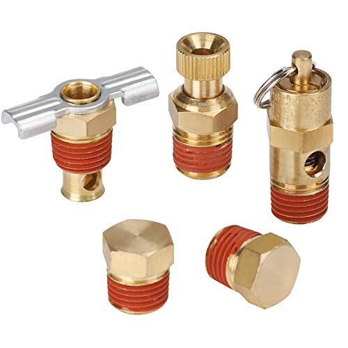
Hromee 5-Piece 1/4-Inch Drain Valve Kit
This brass fitting assortment provides essential replacement valves and plugs for routine compressor tank maintenance. It pairs winged and knurled drain petcocks with a 140 PSI safety relief valve for dependable pneumatic management.
Pros
- Solid brass body provides corrosion and heat resistance
- Two petcock styles offer flexible moisture draining options
- Integrated safety valve handles up to 55 SCFM flow
- Stainless steel relief components resist rust over time
Cons
- Requires separate thread sealant for proper sealing
- Safety valve maximum pressure is capped at 140 PSI
- Winged drain handle has a 12-pound torque limit
Hromee Automatic Air Compressor Tank Drain Valve
The Hromee Automatic Air Compressor Tank Drain Valve Kit automates moisture removal from pneumatic receiver tanks and filters using an adjustable electronic timer and durable braided steel hose. It is an ideal preventative upgrade for garage hobbyists, woodworkers, and shop owners looking to protect their air equipment from internal rust without manual draining.
Pros
- Fully adjustable cycle and duration timers match purge frequency to workshop humidity levels
- Extensive adapter collection fits common 1/4-inch, 3/8-inch, and 1/2-inch NPT tank drain ports
- Braided steel lead hose provides generous clearance to route moisture away from hard-to-reach petcocks
- Pre-wired 6-foot grounded 110V-120V plug eliminates the need for electrical hardwiring
- IP65 enclosure provides dependable protection against dust and workshop moisture
Cons
- Requires an accessible 110V-120V electrical outlet positioned near the compressor location
- Minimum operating ambient temperature of 32°F makes it unsuitable for unheated sub-freezing shops
- Audible pressurized purge bursts may startle users inside small, quiet residential garages
Hromee Air Tank Manifold Replacement with Fill
The Hromee Air Tank Manifold is a heavy-duty brass replacement assembly engineered to restore portable air carry tanks with a durable aluminum shut-off knob, Schrader fill valve, and 125-150 PSI safety bypass. It offers an easy, dependable rebuild solution for DIYers and mobile mechanics fixing leaking portable air bubbles.
Pros
- Durable solid brass body and stainless steel spring resist internal moisture corrosion
- Machined aluminum shut-off knob provides far greater longevity than fragile plastic turn valves
- Integrated 125-150 PSI safety relief valve includes a manual pull ring for pressure venting
- Standardized port threads allow straightforward installation of gauges, hoses, and quick-connect couplers
Cons
- Inlet thread is fixed at 1/2-inch MNPT, requiring step-down bushings for tanks with alternative port sizes
- Pop-off safety valve threshold of 125-150 PSI makes it unsuitable for high-pressure systems rated over 150 PSI
- Requires proper thread sealant or quality PTFE tape during installation to prevent hairline air leaks
SUNROAD 10-Inch Compressor Tank Drain Kit
Draining moisture prevents compressor tank rust, and this SUNROAD kit simplifies routine maintenance with a flexible braided steel line and an accessible quarter-turn shutoff. It provides a practical upgrade for standard 1/4-inch and 3/8-inch drain ports operating under 175 PSI.
Pros
- Durable braided steel hose prevents kinks
- Corrosion-resistant chrome-plated brass valve
- Complete installation kit with clamps and tape
- Rubber-coated handle allows easy quarter-turn operation
Cons
- 10-inch hose may be short for large tanks
- Working pressure is limited to 175 PSI
- Requires manual operation after every compressor use
Plumbing an Auxiliary Air Tank to Expand Pneumatic Capacity
Expanding your compressed air system with an auxiliary reservoir is one of the most effective modifications for dealing with air-hungry tools in a home garage or workshop. Before you start threading fittings together, you must understand how air volume and pump displacement interact under load. Connecting a secondary vessel requires precise component matching to keep the entire pressure system safe, balanced, and leak-free.
The Mechanics of Air Storage: Understanding CFM Output Versus Buffer Volume
Many compressor owners mistakenly believe that adding an auxiliary reservoir increases the actual delivery capacity of their air compressor. An air compressor pump produces a specific volume of pressurized air, measured in cubic feet per minute at a given pressure like ninety PSI. A secondary tank does not alter pump displacement, motor horsepower, or compression efficiency. Instead, an extra tank simply acts as a mechanical buffer or energy battery that stores pressurized air produced over time.
This air buffer provides immense value during intermittent, high-volume pneumatic tasks. When you fire a heavy-duty pneumatic impact wrench or run a framing nailer rapidly, the tool consumes far more air than a compact one-horsepower pump can generate in real time. The extra tank absorbs this sudden consumption surge, holding working line pressure steady rather than allowing an immediate pressure drop. Once the tool stops firing, the compressor pump continues running to refill both vessels back to maximum cut-out pressure.
Problems arise when users attempt to power continuous-demand pneumatic tools like rotary sanders or paint sprayers on an undersized compressor pump connected to an enormous tank. A continuous tool eventually drains the entire multi-tank reserve down to the pump’s cut-in threshold. At that point, the air pressure stabilizes only at whatever flow the bare pump can continuously supply, leaving the tool underpowered. Sizing your storage expansion requires balancing your specific tool duty cycles against the recovery capacity of your electric motor.
Direct Tank-to-Tank Plumbing Versus Downstream Regulated Expansion
You can configure an auxiliary air tank in two primary ways: unregulated parallel plumbing or downstream regulated staging. Direct unregulated plumbing bridges the two air vessels together before any line regulator, allowing both tanks to share identical internal pressure. In this setup, the primary tank and the secondary tank fill simultaneously up to the compressor pressure switch cut-out setting, which often ranges between 125 PSI and 175 PSI. Both vessels act as a single, combined pressure vessel.
An unregulated parallel connection requires that the secondary vessel holds a maximum working pressure rating equal to or greater than the primary tank. If your main compressor cuts out at 150 PSI, the auxiliary vessel must be rated safely for at least 150 PSI or higher. You must also ensure that the compressor unloader valve and pressure switch remain on the primary pump manifold. The pump will pressurize both tanks equally, and the pressure switch will shut the motor off only when both tanks reach peak cut-out pressure.
Downstream regulated expansion places the secondary reservoir after the primary compressor’s pressure regulator. In this configuration, the main tank holds high storage pressure, while the secondary tank receives air regulated down to a specific working pressure, such as ninety PSI. This arrangement works well when the secondary tank is an older portable carry tank with a lower working pressure rating. However, it restricts the stored energy in the auxiliary tank because lower operating pressure stores significantly less usable mass of compressed air.
Essential Fittings, Manifolds, and Pressure Relief Safety Hardware
Connecting pressure vessels requires heavy-duty brass fittings, reinforced hoses, and strict adherence to pressure ratings. Air tanks typically feature National Pipe Taper thread ports, commonly sized in 1/4-inch, 3/8-inch, or 1/2-inch NPT bungs. Using solid brass bushings and adapters prevents galvanic corrosion and ensures airtight mechanical seals under cyclic vibration. Thread sealant tape or anaerobic paste must be applied evenly across all male pipe threads to eliminate micro-leaks that force the pump to cycle during idle periods.
Every auxiliary tank must feature its own certified safety relief valve to prevent catastrophic pressure vessel failure. If an obstruction occurs in the interconnecting line or a shut-off valve is closed while the pump runs, an unprotected tank could exceed its structural limit. Installing a dedicated brass safety pop-off valve, such as a 140 PSI relief valve with a stainless steel pull ring, ensures the auxiliary tank will vent excess pressure automatically if line pressure surges beyond safe working thresholds.
Installing a multi-port manifold assembly on the auxiliary tank simplifies setup and operation considerably. Hardware like the Hromee Air Tank Manifold Tool provides an integrated aluminum shut-off valve, a built-in safety relief bypass, a 1/8-inch NPT pressure gauge port, and an auxiliary Schrader tire fill valve. This design threads directly into a standard 1/2-inch NPT tank bung, giving you an immediate 1/4-inch NPT discharge port while preserving crucial pressure monitoring and manual shut-off control. When connecting lines, using solid brass hex head plugs to seal unused tank ports maintains complete structural integrity.
Step-by-Step Plumbing Procedure for an Auxiliary Air Tank
Begin by completely disconnecting the air compressor from electrical power and opening all drain valves to exhaust stored pressure until the tank gauge reads zero PSI. Never loosen fittings, plugs, or manifold adapters on a pressurized vessel, as escaping high-pressure air can launch brass hardware dangerously. Once the system is depressurized, inspect the secondary tank internally and externally for any signs of rust, dents, or metal fatigue before proceeding with the installation.
Remove the bung plug from an unused service port on the primary air compressor tank or plumb a brass tee fitting into the line between the tank and the pressure regulator. Apply several wraps of PTFE thread sealing tape in a clockwise direction across the male threads of your brass adapter. Thread the fittings into place and tighten them securely with smooth-jawed wrenches, taking care not to overtighten brass components and crack the threads.
Connect the intermediate transfer line between the primary compressor bung and the auxiliary tank inlet. For a permanent workshop setup, you can use rigid copper pipe or schedule-rated steel piping with flexible whip hoses to absorb motor vibration. For a semi-portable configuration, use a high-flow braided hose with 1/4-inch or 3/8-inch NPT ends rated for your system maximum operating pressure. Incorporating a heavy-duty brass ball valve on the connecting line allows you to isolate the secondary tank whenever you only need quick, small-volume compressor operations.
Close all drain valves, restore electrical power, and allow the compressor to pressurize the combined system up to the factory cut-out threshold. As the pressure builds, listen closely for hissing sounds around all new thread joints and manifold bungs. Spray a solution of soapy water or dedicated bubble leak detector over every connection; any forming bubbles indicate an active leak that must be depressurized and resealed before putting the pneumatic system into service.
Managing Condensation and Moisture Across Multiple Storage Vessels
Expanding your storage capacity significantly increases the total volume of air processed, which multiplies the amount of water condensation collecting inside your tanks. When ambient air is compressed, its relative humidity rises rapidly, forcing moisture vapor to condense against the cool steel tank walls. Water pooling in the bottom of an air tank causes severe internal oxidation, thinning the metal over time and risking vessel rupture, while also sending rusty water droplets down your air lines into sensitive pneumatic tools.
Both the primary air compressor and the auxiliary tank require daily moisture draining to maintain safety and air purity. Factory drain petcocks with knurled thumb twists or winged drain cocks can become stiff, corroded, and awkward to operate beneath heavy tanks. Installing an extended drain kit, such as the SUNROAD or QWORK 10-inch braided steel drain hose assemblies, relocates the drain port to an easily accessible position. These assemblies feature quarter-turn chrome-plated brass ball valves rated to 175 PSI, making routine condensation purges effortless after every workday.
For high-volume workshops where manual draining might be forgotten, an electronic automatic drain valve provides reliable protection. Units like the Hromee Automatic Air Compressor Tank Drain Valve feature programmable interval timers that open an electronic solenoid valve for several seconds at preset intervals. Powered by standard household 110V to 120V alternating current, these automatic assemblies eject accumulated water and sludge through braided lines without requiring operator intervention, keeping your auxiliary vessels dry and rust-free throughout intensive projects.
Compressor Duty Cycles, Thermal Heat Dissipation, and Motor Strain
Adding a secondary air tank substantially increases the time your compressor pump must run continuously to reach full cut-out pressure. A portable six-gallon pancake or hot dog compressor pump that normally builds pressure in two minutes might require four to six continuous minutes of runtime to fill an added ten-gallon tank from empty. You must evaluate your compressor motor duty cycle to avoid causing thermal overload or premature mechanical failure.
Most consumer and prosumer oil-free electric air compressors carry a fifty percent duty cycle rating, meaning the pump should rest as much time as it runs during any given operational window. When a small pump runs without interruption to pressurize thirty gallons of total storage, the cylinder heads, piston seals, and reed valves reach elevated operating temperatures. Excessive heat degrades PTFE piston rings in oil-free units and thins lubricating oil in splash-lubricated cast-iron pumps, causing accelerated valve plate wear.
If your compressor trips its thermal overload breaker during the initial fill of both tanks, your combined storage volume is likely too large for the motor displacement. To manage this heat buildup, allow the main compressor to reach full cut-out pressure first, then open the isolation valve slowly to charge the auxiliary tank in stages. Alternatively, consider using the secondary tank only during specific jobs that genuinely demand high-burst air volume rather than leaving it plumbed permanently into daily light-duty operations.
Eliminating Airflow Bottlenecks and Pressure Drop Across Interconnect Lines
The physical diameter of your connecting lines and couplers dictates how efficiently air transfers between tanks during heavy tool usage. Standard 1/4-inch automotive or industrial quick-connect couplers create substantial pneumatic restriction when high CFM flows pass through their small internal orifices. If you connect an extra tank through restrictive 1/4-inch fittings, the secondary tank cannot discharge its stored energy quickly enough to prevent pressure drop at your tool.
To maintain maximum airflow, plumb intermediate lines using 3/8-inch or 1/2-inch internal diameter lines with high-flow brass couplings. Connecting directly into tank bungs using full-port brass fittings provides unrestricted air exchange between the vessels, allowing both tanks to react instantly to tool demand. Keeping line lengths as short as practical between the primary compressor and auxiliary vessel also minimizes frictional resistance and preserves static line pressure.
Place your final working pressure regulator and moisture separator filter downstream of both storage tanks. Positioning the regulator after the secondary vessel ensures that all stored air is cleaned, dried, and regulated to a consistent working pressure before reaching your air hose. This configuration guarantees that your pneumatic impact wrenches, nailers, and inflators receive stable, dry airflow while maximizing the energy stored across your expanded compressor system.
Final Verification and Long-Term Auxiliary Tank Maintenance
Once your auxiliary air tank is securely plumbed, perform regular visual inspections and pressure checks to maintain peak operational reliability. Inspect all braided lines, mounting clamps, and brass adapters for vibration wear, and test your secondary safety relief valve monthly by pulling the manual release ring while the system holds moderate pressure. Keeping connections sealed, draining tank water faithfully after every session, and respecting your compressor pump duty limits ensures your expanded air delivery setup will provide dependable pneumatic power for years to come.
About the author
Kenny Koehler is a power-tool specialist with more than a decade of hands-on evaluation experience and a science-based approach to product testing. His expertise in repeatable testing, tool performance, impact wrenches, and professional equipment brings a practical, data-focused perspective to compressor and pneumatic-tool comparisons.