
How to Convert Electric Air Compressor to Gas Engine: Practical Guide for 2026
How To Convert Electric Air Compressor To Gas Engine steps for October 2026: calculate pulley ratios, mount gas engines, and install continuous-run pilot unloader valves.
 By Tony Carrick
Updated October 8, 2026
By Tony Carrick
Updated October 8, 2026

Remote jobsites and mobile service trailers often lack access to dedicated electrical circuits, stranding high-demand pneumatic tools when portable generators struggle under severe motor startup inrush current. Learning how to convert electric air compressor to gas engine configurations allows tradespeople and mechanics to repurpose reliable cast-iron pumps onto independent, fuel-powered platforms. This conversion transforms stationary or shop-bound compressors into autonomous workhorses capable of running framing nailers, impact wrenches, and paint sprayers anywhere. The process involves mechanical alignment, precise horsepower calculations, and specialized continuous-run pneumatic valving.
Converting an electric compressor requires far more than unbolting an electric motor and bolting down a small gas engine. Electric air compressors rely on pressure switches that cycle power on and off, but small gasoline engines must run continuously while alternating between compression and idle states. Installing dedicated components like a pilot unloader valve and an engine throttle control ensures the pump vents head pressure safely when the air tank fills. Understanding the engineering behind pulley ratios, engine displacement, and unloading controls helps you build a dependable, high-output gas air compressor that handles rugged field duties.
| Award | Product | ACR Score About ACR ScoreThe ACR Score is our own rating from 0 to 10, based on performance, design and build, ease of use, and value. It reflects independent research and is never influenced by manufacturers, retailers, or affiliate commissions. Learn more › | |
|---|---|---|---|
| Best Overall |
Pro-Edge 1/2" NPT Unloader Valve with Cable
|
9.2/10 | Buy |
| Best Budget |
 Conrader TCSP-H-5565 Throttle Control
|
9.1/10 | Buy |
| Best Value |
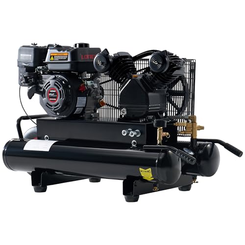 Albott 6.5HP 8-Gallon Gas Air Compressor
|
9.1/10 | Buy |
 Air Lift 16060 12V Air Compressor
|
8.6/10 | Buy | |
| Best Premium |
 VEVOR 13.2-Gallon 7HP Gas Air Compressor
|
8.6/10 | Buy |
 Compressor-Source 125-150 PSI Pilot Valve
|
8.4/10 | Buy | |
 Rolair 131B Pilot Unloader Valve, 125-150 PSI
|
8.1/10 | Buy | |
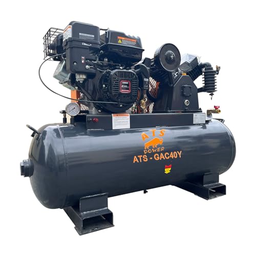 Generic 40-Gallon 15HP Gas Air Compressor
|
8.0/10 | Buy | |
 Metabo HPT EC2510E 8-Gallon Air Compressor
|
7.8/10 | Buy |
Pro-Edge 1/2" NPT Unloader Valve with Cable
Built for gas-powered air compressors up to 6.5 HP, this Pro-Edge setup combines a pilot, check, and unloader valve with a 36-inch throttle control cable. Its heavy-duty brass construction reliably manages engine idling and cycling under demanding outdoor conditions.
Pros
- Combines pilot, check, and unloader valves in one unit
- Sturdy all-brass construction resists outdoor wear
- Comes with manual unloader toggle and brass muffler
- Broad operating temperature range up to 400 degrees Fahrenheit
- Includes 36-inch throttle cable with Z-bend connector
Cons
- Limited to gas engines rated 6.5 HP and below
- Requires minimum 80 PSI for throttle cable operation
- Fixed factory pressure setting of 95 to 125 PSI
Conrader TCSP-H-5565 Throttle Control
Built for gas-powered air compressors, the Conrader TCSP-H-5565 regulates throttle operation on 5.5 to 6.5 HP Honda and clone engines. It features a standard 1/4-inch compression inlet, making it a focused replacement component for workshop and jobsite compressor maintenance.
Pros
- Direct fit for 5.5 to 6.5 HP Honda engines
- Compatible with genuine and clone gas engines
- Standard 1/4-inch compression inlet fitting
- Dedicated throttle regulation for air compressors
Cons
- Not compatible with engines outside 5.5 to 6.5 HP
- Restricted to gas-powered compressor setups
Albott 6.5HP 8-Gallon Gas Air Compressor
Built for off-grid job sites, this gas-powered unit delivers reliable pneumatic power with a 6.5 HP engine and a two-cylinder cast iron pump. Dual air outlets let two operators run tools simultaneously without depending on electrical hookups.
Pros
- Rugged cast iron pump and frame construction
- Dual air outlets support two simultaneous tools
- Gas-powered design eliminates need for electrical outlets
- Automatic safety valve ensures steady pressure management
Cons
- Very heavy at 166 pounds
- Modest 115 PSI maximum working pressure
- Substantial footprint requires ample vehicle cargo space
Air Lift 16060 12V Air Compressor
Built for automotive air suspension setups, the Air Lift 16060 delivers onboard pneumatic support in a compact package weighing under two pounds. Its modest footprint makes it an easy fit for drivers seeking a dedicated 12V compressor that can mount into tight vehicle spaces.
Pros
- Lightweight construction under two pounds
- Compact size fits tight underbody spaces
- Standard 12-volt vehicle power compatibility
- Manufactured in the United States
Cons
- Restricted to 12V automotive power sources
- Requires separate air lines and fittings
VEVOR 13.2-Gallon 7HP Gas Air Compressor
Built for job sites lacking electrical hookups, this gas-powered VEVOR unit pairs a 7HP engine with dual outlets to run two pneumatic tools simultaneously. The 9 CFM delivery rate at 115 PSI ensures fast recovery times for outdoor construction and workshop tasks.
Pros
- Dual outlets operate two pneumatic tools at once
- Strong 9 CFM airflow provides rapid air delivery
- Automatic low-oil shutoff prevents pump damage
- Sturdy cast iron cylinders and frame construction
Cons
- Heavy unit weighing over 131 pounds
- Maximum pressure limited to 115 PSI
- Gas-powered design requires regular engine maintenance
Compressor-Source 125-150 PSI Pilot Valve
Manufactured in the USA by Conrader, this pilot valve regulates discharge and throttle control across a dedicated 125 to 150 PSI operational window. Its all-brass construction offers reliable durability for air systems requiring a standard 1/4-inch male NPT fitting.
Pros
- Durable all-brass construction
- Standard 1/4-inch male NPT connection
- Compact 4-inch profile fits tight spaces
- Manufactured in the USA by Conrader
Cons
- Restricted to 125 to 150 PSI applications
- Requires adapters for non-quarter-inch ports
Rolair 131B Pilot Unloader Valve, 125-150 PSI
The Rolair 131B pilot unloader valve provides reliable pressure regulation for compatible air compressors, arriving factory preset for 125 to 150 PSI operation. Equipped with a built-in muffler vent and pressure adjustment capability, it serves as a direct service replacement for Rolair, Jenny, and Emglo models.
Pros
- Factory preset for standard 125 to 150 PSI operation
- Pressure levels can be adjusted manually
- Includes muffler vent for quieter discharge
- Broad compatibility with Rolair, Jenny, and Emglo units
Cons
- Compatibility is restricted to specific compressor models
- Requires manual calibration for non-standard pressure requirements
Generic 40-Gallon 15HP Gas Air Compressor
Built for demanding pneumatic tools like sandblasters and impact wrenches, this two-stage compressor pairs a 420cc RATO gas engine with a 40-gallon ASME tank. It delivers 24 CFM at up to 175 psi, providing reliable air delivery for off-grid job sites and busy workshops.
Pros
- High 24 CFM output powers demanding pneumatic tools
- Electric and recoil start provide flexible operation
- Durable ASME-certified steel pressure tank
- Oil-free pump minimizes routine maintenance tasks
- Integrated low-oil shutdown protects the engine
Cons
- Very heavy unit at 360 pounds
- Gas engine requires outdoor or well-ventilated placement
- Large footprint demands significant floor space
Metabo HPT EC2510E 8-Gallon Air Compressor
Built for job sites without electrical hookups, this Metabo HPT compressor pairs a dependable Honda GX engine with an 8-gallon tank to power demanding framing and roofing nailers. Its cast iron pump and protective control panel suit rugged field use, though its 144-pound heft demands serious effort to haul.
Pros
- Reliable Honda GX gas engine
- Durable cast iron cylinder design
- Protective baseplate shields gauges and plumbing
- Delivers up to 145 PSI pressure
- Pre-installed 3/8-inch locking regulator
Cons
- Very heavy at 144 pounds to transport
- Gas engine requires outdoor ventilation and fuel upkeep
- Standard 1-year warranty is relatively short
Engineering a Gas Engine Conversion for Electric Air Compressors
Transforming an electrically driven compressor into an autonomous gasoline-powered system solves the persistent problem of running high-draw pneumatic equipment in off-grid environments. Successful conversions demand a thorough understanding of continuous-run pneumatic circuits, mechanical power transmission, and engine governor mechanics.
The Fundamental Difference Between Electric and Gas Compressor Control Systems
Electric air compressors operate on a simple start-and-stop control logic dictated by an electro-mechanical pressure switch. When tank pressure falls below the cut-in setpoint, contacts snap closed, drawing electrical line current to spin the electric motor until reaching cut-out pressure. Once full, the switch cuts power instantly and bleeds head pressure through a tiny unloader valve to prepare for the next startup cycle. That cycle stops the rotating assembly entirely while air reserves remain satisfied.
A small gasoline engine cannot be rapidly switched off and restarted every time the compressor tank pressure drops. Stopping and pulling a recoil starter or cycling an electric starter dozens of times an hour would quickly ruin the engine, drain starting batteries, and interrupt jobsite workflows. Instead, gas-driven compressors must operate on a continuous-run system where the gasoline engine runs uninterrupted while the compressor cycles. This operational requirement represents the single most critical conceptual hurdle when planning a gas conversion project.
Continuous-run operation requires a mechanical pilot unloader valve paired with an integrated or remote check valve. When the air tank hits cut-out pressure, the pilot valve detects the threshold and redirects compressed air to vent pump discharge to atmosphere or unseat pump intake valves. At the exact same moment, the valve routes pneumatic pilot pressure to an engine throttle control actuator. This dual-action response unloads compression resistance and forces the gas engine to drop down to idle speed until tank pressure drops back to cut-in.
Engine Sizing and Horsepower Conversion Math
Sizing a replacement gas engine requires understanding the practical difference between electric motor horsepower ratings and internal combustion engine output. Electric motors generate maximum torque at zero RPM and sustain strong torque across their entire operating range with substantial service factors. Small four-stroke gasoline engines produce peak torque across a narrower power band and operate against governed throttle responses. As a general engineering rule, a gasoline engine must be sized approximately 1.5 to 2 times larger than the rated continuous horsepower of the electric motor it replaces.
A single-stage compressor pump previously powered by a typical 2-horsepower electric motor normally demands a 5.5-horsepower to 6.5-horsepower gasoline engine. Engines in this class, such as common small-displacement overhead valve units, provide sufficient low-end rotational torque to carry the compressor pump through high-pressure cycles without bogging down. If the pump is an intermediate two-cylinder unit that originally drew high amperage on a dedicated 240-volt line, a 7-horsepower gas engine provides comfortable operating headroom. Matching this output ensures the engine does not overheat or stall as tank pressure approaches its upper limit.
Larger two-stage cast-iron pumps require substantial displacement increases to achieve continuous air delivery. Heavy-duty pumps pushing 15 to 25 cubic feet per minute at high pressure will quickly overload smaller utility engines. Industrial installations often step up to engines displacing 420 cubic centimeters or delivering around 15 horsepower. An engine of that size provides the rotational force needed to spin multi-cylinder pumps up to 175 PSI without excessive thermal strain.
Pulley Ratios and Pump RPM Calculations
Operating speed differences between electric motors and small gasoline engines require careful recalculation of drive pulley diameters. Most standard four-pole electric compressor motors turn at roughly 1,725 RPM, while two-pole electric motors run at 3,450 RPM. Small single-cylinder gasoline engines operate with internal governors tuned to an unloaded operating speed of 3,600 RPM. Connecting a gas engine directly with existing electric motor pulleys will cause pump overspeeding, severe vibration, and immediate valve plate destruction.
Calculating the correct engine pulley diameter relies on the standard rotational speed ratio formula. You must multiply the target pump rotational speed by the pump flywheel pitch diameter, then divide that figure by the governed engine speed of 3,600 RPM. Most splash-lubricated cast-iron pumps are designed to operate safely between 700 and 1,200 RPM to maintain adequate oil throw and prevent connecting rod failure. Applying this math typically dictates installing a significantly smaller drive pulley on the engine crankshaft than was present on a 1,725 RPM electric motor.
Belt alignment and groove profile matching are equally critical when fabricating the drive assembly. Misaligned V-belts generate rapid friction heat, shred rubber cords, and introduce damaging radial side-loads onto the pump crankshaft bearings. You should use a rigid straightedge across the machined outer faces of the engine drive pulley and pump flywheel to verify zero angular misalignment. Maintaining proper belt tension allows efficient power transfer without putting excessive static strain on the engine crankshaft seal.
Essential Pneumatic Control Hardware: Pilot Unloaders and Throttle Actuators
A continuous-run conversion cannot function without specialized pneumatic valving that replaces the electrical pressure switch. An all-in-one combination pilot unloader check valve provides the most straightforward plumbing solution for small to mid-sized conversions. Valves in this category, such as the PRO-EDGE brass combination valve, combine the high-pressure tank check valve, pilot sensing mechanism, and continuous discharge unloader into a single compact casting. This integrated layout eliminates complex inter-pipe fittings and reduces leak points on tight compressor saddles.
Standalone pilot valves, such as Conrader or Rolair pilot controls, offer an alternative configuration for custom plumbing arrangements. These precision brass valves mount directly into a tank port to continuously monitor storage reservoir pressure. When tank air reaches the factory setting, typically between 125 and 150 PSI, the pilot valve pops open an internal ball or piston. This action vents compressed air through an exhaust muffler while simultaneously sending pressure through a 1/4-inch copper or nylon tube to an unloader head or engine control.
The engine throttle control, commonly known as a cable throttle control or pneumatic bullwhip, acts as the physical link between the air tank and the engine governor. When the pilot valve unloads, air pressure enters the throttle control body, pushing a spring-loaded piston and inner control cable outward. This cable attaches directly to the engine throttle arm, overriding the governor spring to idle the engine down to roughly 1,800 to 2,000 RPM. When tank pressure falls to cut-in level, the pilot valve exhausts, the throttle control spring retracts, and the engine snaps back to full 3,600 RPM operating speed.
Mounting, Vibration Isolation, and Baseplate Fabrication
Internal combustion engines generate significantly higher harmonic vibration and rotational pulsation than smooth electric induction motors. The factory baseplate or saddle bracket welded to an electric compressor tank was generally designed to support a balanced electric motor. Bolting a reciprocating four-stroke gas engine directly to a lightweight stamped steel saddle can create stress fractures in the tank bracket or tank shell over time. Reinforcing the saddle with a heavy steel adapter plate distributes operating forces across a larger surface area.
The engine mounting plate must feature slotted bolt holes or an adjustable slide track to allow precise belt tensioning and tracking. Because the gas engine crankshaft sits at a specific height, you must confirm that the engine clears the tank circumference and flywheel rim without interference. Rigid steel plate measuring at least 3/16-inch or 1/4-inch thickness provides the stiffness required to prevent motor plate flexing under full compression torque. Any flex in the plate allows the drive belt to loosen dynamically, causing slip and rapid belt glazing.
Vibration isolation should focus on preserving structural welds and protecting sensitive pneumatic lines from fatigue. Heavy rubber vibration isolators placed under tank mounting feet prevent the entire compressor assembly from walking across jobsite surfaces. However, avoid placing soft rubber pads directly between the engine and the pump mounting deck. Flexible engine mounts cause the distance between the drive pulley and pump flywheel to shift under acceleration, resulting in erratic belt flutter and belt throwing.
Step-by-Step Conversion and Assembly Procedure
The conversion begins with absolute safety preparation and complete system depressurization. Disconnect the compressor from all electrical supplies, lock out switches, and pull the ASME safety relief valve ring to exhaust all stored air from the tank. Open the bottom tank drain valve completely to confirm that zero residual pressure remains inside the reservoir. Remove the existing electric motor, pressure switch, electrical conduit, and drive belt, setting aside the mounting hardware for evaluation.
Position the replacement gas engine on the reinforced baseplate to check crankshaft alignment with the pump flywheel. Install the calculated drive pulley onto the engine crankshaft using a matching keyway and set screws secured with medium-strength threadlocker. Align the drive pulley with the pump flywheel using a machinist straightedge to verify parallel plane alignment. Snug the engine mounting bolts in their adjustment slots, tension the drive belt according to belt specifications, and tighten all base fasteners securely.
Plumb the pneumatic discharge and pilot unloader circuit to establish the continuous-run system. Thread the combination pilot unloader check valve into the primary tank inlet port using appropriate thread sealant designed for high-temperature vibration environments. Connect the high-pressure discharge line running from the compressor pump head directly to the inlet port of the unloader valve. Install a secondary 1/4-inch copper or reinforced nylon tubing run from the pilot unloader signal port over to the throttle control mechanism.
Mount the throttle control bracket to the engine block adjacent to the carburetor and governor control linkage. Insert the Z-bend end of the throttle control cable into the throttle lever hole on the engine control bracket. Adjust the cable casing bracket position so that the engine operates at full governed speed when the pilot valve is closed and the cable is retracted. When pressurized air pushes the cable outward, the stroke must move the throttle arm firmly against the idle speed adjustment screw without binding the governor mechanism.
Calibrating Operating Pressures, Idle Speeds, and Safety Relief Systems
Once mechanical assembly is complete, testing begins with a controlled pressure calibration process. Check that both the compressor pump crankcase and the engine crankcase contain fresh, clean oil filled to proper sight-glass or dipstick levels. Start the gasoline engine with the manual unloader toggle valve flipped to the open position, allowing the engine to warm up under zero compression resistance. Once warm, flip the manual toggle closed and observe tank pressure rise while monitoring the pressure gauge closely.
Note the exact pressure reading where the pilot valve triggers and vents pump discharge air through its exhaust port. If using an adjustable pilot valve, such as a Rolair 131B style valve, adjust the differential screw to match your desired cut-out threshold, typically around 125 to 150 PSI. Confirm that the pilot valve exhausts cleanly with a distinct snap rather than a sluggish hiss. The engine should immediately drop to a smooth idle once the unloader vents discharge pressure.
Verify that the ASME-certified safety relief valve installed on the tank is rated appropriately for your storage vessel. The safety valve pressure rating must never exceed the tank manufacturer maximum allowable working pressure stamped on the tank data plate. Inspect the safety valve ring before daily operation to confirm free movement and verify that it seats tightly without leaking air. Never operate a converted air compressor with a plugged, modified, or stuck safety relief valve under any circumstances.
Conversion Feasibility: DIY Repowering Versus Dedicated Factory Gas Compressors
Evaluating whether to build a custom conversion or invest in a factory-built gas air compressor depends on existing equipment quality and budget reality. If you already possess an industrial-grade cast-iron pump attached to a solid ASME tank with a burned-out electric motor, repowering makes economic sense. Sourcing a small utility engine, pilot unloader valve, throttle control cable, and drive pulley can resurrect expensive cast-iron hardware for a fraction of replacement equipment expense. However, older consumer-grade pumps with light aluminum components may not justify the labor and hardware investment.
Factory-built gas air compressors provide integrated convenience, balanced frame engineering, and turnkey warranty support. Models like an 8-gallon wheeled contractor compressor powered by a 6.5-horsepower engine or a Honda GX powerplant arrive with pre-calibrated continuous-run valving and rugged roll cages. Portable wheelbarrow designs, such as VEVOR 13.2-gallon units or Metabo HPT contractor units, feature balanced weight distribution tailored specifically for truck bed transit and rough jobsite movement. For working contractors whose billable hours dictate equipment choices, turnkey units eliminate trial-and-error fabrication.
High-volume commercial requirements also tilt the decision toward purpose-built industrial machinery. When powering continuous sandblasting setups, dual-action sanders, or multiple heavy impact wrenches, a small conversion will struggle to keep pace. Stationary or skid-mounted units featuring 15-horsepower engines and two-stage 40-gallon tanks generate upwards of 24 CFM at 175 PSI with complete factory reliability. Assessing your sustained CFM demand at 90 PSI clarifies whether a DIY repower fits your workload or if an industrial-grade factory package is necessary.
Long-Term Maintenance for Gas-Converted Air Compressors
Operating a gas-powered compressor requires maintaining two independent mechanical power units subject to rugged environmental conditions. Small gasoline engines require regular engine oil changes, spark plug inspections, and air cleaner servicing to prevent premature piston ring wear. Because outdoor jobsite environments expose equipment to fine sawdust, drywall powder, and masonry debris, foam pre-cleaners must be inspected frequently. Inspecting engine baseplate bolts and belt guard brackets every few operating hours prevents vibration from backing out critical fasteners.
Compressor pump maintenance shifts depending on lubrication architecture and operating temperatures. Splash-lubricated cast-iron pumps require non-detergent ISO 68 or ISO 100 compressor oil, as automotive detergent oils can cause foaming and valve carbonization. Check the pump oil sight glass before every engine pull start, maintaining oil levels dead center on the indicator dot. Outdoor operation in cold weather requires careful oil viscosity selection to prevent high startup drag from straining the engine recoil mechanism.
Daily moisture draining remains mandatory for preserving pressure vessel integrity on converted units. Compressed air cooling inside the steel reservoir naturally deposits liquid condensation at the bottom of the tank. Allowing acidic water to pool inside the vessel causes severe internal rust and pinhole leaks that ruin the air tank. Purging the bottom drain valve after every workday releases collected moisture and keeps pneumatic lines feeding dry, clean air to downstream air tools.
Operational Verification and Safe Field Startup
Field reliability depends on disciplined operational habits every time you fire up a gas-converted compressor. Always inspect the drive belt condition, belt guard security, and engine fuel shutoff valve before pulling the starter cord. If starting in cold weather, flip the manual unloader toggle on the pilot valve to vent pump discharge to atmosphere. This step eliminates compression resistance against the pump pistons, allowing the engine to start effortlessly without fighting backpressure.
Allow the gasoline engine to run at idle for two to three minutes to reach operating temperature before closing the manual unloader valve. Once closed, observe the first complete cycle as the pump fills the tank, verifying that the throttle snaps down cleanly at your target cut-out pressure. Check all tube connections with a soapy water solution periodically to detect small air leaks around compression fittings before they degrade cycling efficiency. Taking these practical verification steps ensures your converted pneumatic power system delivers reliable, heavy-duty air supply across years of demanding field projects.
About the author
Tony Carrick is an experienced product researcher and writer specializing in tools, home improvement, automotive maintenance, and consumer equipment. With extensive experience reviewing tools and tackling hands-on renovation projects, he brings a buyer-focused perspective to compressor performance, usability, and overall value.