
How to Connect Two Air Compressors: Practical Guide for 2026
Learn how to connect two air compressors in parallel for higher CFM delivery and steady tool pressure during October 2026 workshop projects.
 By Tom Scalisi
Updated October 8, 2026
By Tom Scalisi
Updated October 8, 2026

Operating demanding pneumatic tools like continuous rotary sanders or automotive paint sprayers often pushes a single portable compressor past its limits, causing rapid pressure drops and motor overheating. When a single pump cannot maintain adequate cubic feet per minute at ninety PSI, learning how to connect two air compressors provides a practical way to double air volume without buying an expensive commercial rotary screw unit. By joining two separate tanks into a shared pneumatic distribution line, woodworkers and mechanics create a combined reserve that handles high-draw tools smoothly. This dual-compressor configuration bridges the gap between light consumer tanks and heavy industrial equipment, allowing each unit to share the workload during heavy pneumatic cycles.
Successfully linking two machines requires careful mechanical assembly and electrical planning to prevent tripped breakers or backfeeding air lines. Homeowners and shop owners must balance startup inrush current across separate electrical circuits while installing reliable check valves, manifolds, and durable 1/4-inch NPT fittings. Choosing between a synchronized cycle or a staggered lead-lag pressure switch setup ensures both pumps operate efficiently without premature wear. Understanding these key operational principles helps protect your motors, maintain stable regulated line pressure, and keep pneumatic equipment running continuously.
| Award | Product | ACR Score About ACR ScoreThe ACR Score is our own rating from 0 to 10, based on performance, design and build, ease of use, and value. It reflects independent research and is never influenced by manufacturers, retailers, or affiliate commissions. Learn more › | |
|---|---|---|---|
| Best Overall |
FORNAX 2-Way 1/4-Inch NPT Air Manifold
|
9.2/10 | Buy |
| Best Value |
 SARDVISA 22-Piece Kit with 25-Ft PU Hose
|
9.2/10 | Buy |
| Best Premium |
 GERCHWAY 200 PSI Tire Inflator Gauge
|
9.2/10 | Buy |
| Best Budget |
 HHYOOSOO Brass Winterize Blowout Plug (2-Pack)
|
9.1/10 | Buy |
 RNSXYAT 14-Piece 1/4-Inch Air Fitting Kit
|
9.1/10 | Buy | |
 WYNNsky 20-Piece 1/4-Inch NPT Air Compressor
|
8.9/10 | Buy | |
 Hromee Compressed Air Outlet Kit
|
8.9/10 | Buy | |
 JASTIND 4-Piece Air Nozzle Blow Gun Kit
|
8.6/10 | Buy | |
 XAQMHSW 2-Way 1/4-Inch NPT Air Hose Splitter
|
7.8/10 | Buy |
FORNAX 2-Way 1/4-Inch NPT Air Manifold
This compact in-line splitter enables workshops to run two pneumatic tools simultaneously from a single air supply. Built with an aluminum body and steel quick-connect couplers, it offers a simple plug-and-play setup for routine shop tasks.
Pros
- Operates two air tools from one line
- Sturdy steel fittings on lightweight aluminum housing
- Compact footprint under 4 inches long
- Interchangeable with standard 1/4-inch NPT accessories
Cons
- Limited to two output connections
- Rigid straight design can be awkward in tight quarters
SARDVISA 22-Piece Kit with 25-Ft PU Hose
This 22-piece accessory bundle equips home garages and workshops with standard 1/4-inch NPT fittings, dual chucks, and a metal blow gun. Its standout component is a 25-foot coiled PU hose featuring detachable ends that allow easy trimming and repair if damaged.
Pros
- Repairable PU hose design saves replacement costs
- Comprehensive 22-piece selection for inflation and cleaning
- Sturdy metal blow gun supports high air capacity
- Universal 1/4-inch NPT fittings ensure wide compatibility
Cons
- Recommended working pressure is capped at 120 PSI
- Coiled spring hose can limit practical working reach
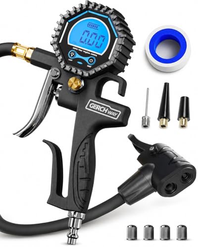
GERCHWAY 200 PSI Tire Inflator Gauge
Equipped with a dual-head chuck for Presta and Schrader valves, this tool handles pressure checks, deflation, and compressor inflation up to 200 PSI. Its 16-inch hose and standard 1/4-inch NPT connector make it well suited for home garage maintenance.
Pros
- Dual-head design works with Presta and Schrader valves
- Accurate readings up to 200 PSI in 0.1 increments
- Performs inflation, air release, and pressure measurement
- 16-inch hose easily reaches tight or awkward valve stems
- Quickly connects to standard 1/4-inch NPT air compressors
Cons
- Requires an external air compressor for tire inflation
- At nearly 0.9 pounds, too bulky for portable kits
HHYOOSOO Brass Winterize Blowout Plug (2-Pack)
Designed for seasonal maintenance, this solid brass blowout plug connects standard air compressors to garden hose threads to purge water from RVs and irrigation lines. It offers a practical way for homeowners and RV owners to protect plumbing from freezing damage.
Pros
- Durable, machined solid lead-free brass build
- Quick 1/4-inch air compressor connection
- Fits standard 3/4-inch garden hose threading
- Versatile for RV, boat, and sprinkler winterizing
- Convenient two-pack configuration
Cons
- Requires a separate air compressor to operate
- Limited to 3/4-inch female hose thread fittings
RNSXYAT 14-Piece 1/4-Inch Air Fitting Kit
Built from solid brass, this 14-piece assortment streamlines air tool connections using an automatic push-to-connect sleeve mechanism. It provides a reliable selection of 1/4-inch NPT couplers and plugs for home garages and automotive workshops.
Pros
- Durable solid brass build resists corrosion and wear
- Quick push-in design connects without retracting the collar
- Six locking balls hold plugs securely in place
- Includes both male and female thread configurations
Cons
- Limited exclusively to 1/4-inch NPT air setups
- Fixed fitting ratios may leave excess unused components
- Heavier overall than comparable aluminum quick-connect fittings
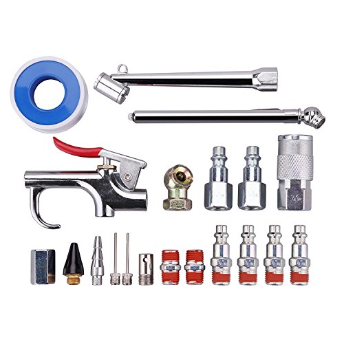
WYNNsky 20-Piece 1/4-Inch NPT Air Compressor
The WYNNsky 20-Piece Air Compressor Accessory Kit provides essential 1/4-inch NPT Industrial interchange couplers, plugs, and inflation attachments backed by pre-coated male threads for fast sealing. It is a practical starter bundle for garage DIYers and home workshop owners setting up a new pneumatic air line.
Pros
- Pre-applied thread sealant on male plugs saves time during initial shop setup
- Wide variety of inflation nozzles and two distinct tire chucks cover multiple garage tasks
- Standard 1/4-inch NPT Industrial interchange matches common pneumatic tool setups
- Included PTFE thread seal tape provides backup sealing for unsealed pipe joints
Cons
- Zinc-plated steel fittings lack the natural corrosion resistance of solid brass over long-term humid shop use
- Kit includes only one quick-connect female coupler despite providing six quick-connect plugs
- Tire gauge tops out at 50 PSI, making it unsuitable for commercial truck, trailer, or high-pressure bicycle tires
Hromee Compressed Air Outlet Kit
The Hromee Compressed Air Outlet Kit provides a modular aluminum distribution drop with push-to-connect fittings and a universal coupler for 1/2-inch tubing networks up to 150 PSI. It is an ideal addition for DIY homeowners and workshop mechanics looking to run clean, dedicated pneumatic lines across their garage walls without dragging long hoses.
Pros
- Solid aluminum block construction with versatile top, back, and side mounting configurations
- Push-to-connect 1/2-inch tube fittings simplify layout modifications without threading rigid pipe
- Includes a dedicated shut-off valve and universal quick-connect coupler out of the box
- Rated for standard pneumatic shop setups up to 150 PSI
Cons
- Requires user-supplied 1/2-inch compressed air tubing and mounting hardware
- Limited to systems operating at or below 150 PSI, excluding high-pressure two-stage 175 PSI drops
- Threaded joints require careful thread sealing tape application to prevent slow micro-leaks
JASTIND 4-Piece Air Nozzle Blow Gun Kit
Built with an all-metal chrome body and an internally pressurized tapered nozzle, the JASTIND blow gun delivers concentrated airflow for clearing debris and dust. The included protective rubber tip prevents surface marring, making it well suited for workshop tasks and electronics cleaning.
Pros
- Durable chrome-plated alloy construction resists wear
- Protective rubber tip prevents scratches on workpieces
- Dual 1/4-inch connection options enhance tool versatility
- Tapered nozzle design easily reaches narrow gaps
Cons
- Requires manual Teflon tape wrapping to prevent air leaks
- Compact body provides limited reach in deep engine bays
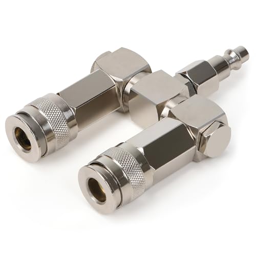
XAQMHSW 2-Way 1/4-Inch NPT Air Hose Splitter
Built for dual-tool setups, this nickel-plated steel manifold splits a single compressor line with full 360-degree swivel mobility to minimize hose tangles. It suits garage and workshop users operating standard pneumatic tools up to 300 PSI.
Pros
- Durable nickel-plated steel construction
- 360-degree swivel design prevents hose binding
- Universal coupler accepts multiple plug profiles
- Quick push-to-connect operation requires no tools
Cons
- Confined to standard 1/4-inch NPT connections
- Maximum working pressure capped at 300 PSI
- Simultaneous dual-tool use can reduce airflow volume
Connecting Dual Air Compressors for High-Demand Pneumatic Tasks
Combining two pneumatic power sources into a unified distribution line resolves severe airflow deficits during demanding shop tasks. When continuous air tools consume more volume than a single pump produces, connecting two machines side by side delivers the necessary volume to stabilize line pressure. Understanding how pressure levels, air volume, and mechanical valves interact ensures a reliable installation.
Parallel Versus Series Plumbing Configurations
Plumbing two compressors together in parallel represents the standard method for increasing air volume in a workshop. In a parallel setup, both compressor discharge lines feed into a common junction manifold before routing toward your primary regulator. This parallel alignment adds individual delivery volumes together, doubling available CFM at ninety PSI while maintaining standard working pressure. Pairing two units that each produce four CFM creates a combined output of eight CFM.
Series plumbing involves piping the compressed outlet of the first machine directly into the air intake of the second machine, presenting severe operational hazards. Standard consumer compressors feature motors and pump heads engineered strictly for ambient atmospheric air. Forcing hot, pre-compressed air into a secondary intake drastically increases compression heat, risking seal failure, cylinder scoring, and motor burnout. Standard air tanks also have maximum pressure limits that series configurations easily exceed.
Parallel connections preserve the independent factory engineering of each machine while pooling air reserves safely. Both units compress ambient air independently and pump volume into their own vessels before merging downstream. This isolation ensures that neither pump experiences abnormal intake pressures or excessive thermal stress during heavy operation. Pneumatic tools benefit from expanded storage capacity and faster pressure recovery without endangering the equipment.
Essential Hardware: Manifolds, Check Valves, and Fittings
Building a dual compressor connection requires robust pneumatic hardware capable of handling high pressure without leaking. Central to this arrangement is a heavy-duty tee fitting or a dedicated multi-port splitter, such as the FORNAX 2-way manifold or the XAQMHSW 2-way splitter. These components allow two independent hose lines to merge into a single distribution port cleanly. Machined aluminum or nickel-plated steel manifolds provide structural durability against vibration and pressure cycles.
Installing one-way inline check valves on the discharge line of each compressor is essential for operational stability and safety. If one machine cycles off while the other continues pumping, pressurized air naturally seeks the path of least resistance and backfeeds into the idle unit. A dedicated brass check valve prevents reverse airflow, directing pressurized air toward the distribution header. Without check valves, pressure differences can cause unloader valves to hiss continuously.
Using quality threaded connectors and couplers, such as solid brass 1/4-inch NPT fittings, guarantees tight seals throughout the assembly. Precision machined threads resist vibration and prevent air leaks that force pumps to cycle unnecessarily. Applying thread sealant tape across all male pipe threads ensures an airtight fit across every connection point. Maintaining consistent fitting diameters prevents artificial bottlenecks that could restrict airflow to your tools.
Managing Electrical Circuit Loads and Startup Surge
Electrical circuit capacity represents the most common obstacle when configuring two electric air compressors in a workshop. Electric compressor motors demand substantial starting inrush current, often pulling up to three times their standard running amperage when starting up. Attempting to run two typical portable compressors on a single 15-amp or 20-amp branch circuit almost always trips the circuit breaker. Even if one machine is already running, the secondary startup surge quickly overloads the circuit.
To operate both machines reliably, each air compressor must plug into a separate, dedicated electrical circuit with adequate breaker sizing. In a typical garage setup, Compressor A connects to a dedicated 120-volt 20-amp branch circuit, while Compressor B plugs into an independent circuit on the panel. Separating electrical loads guarantees that simultaneous motor startups will not overload breakers. If dedicated lines are limited, placing one unit on an alternate receptacle wired to an independent panel breaker is required.
Avoiding light-duty extension cords is equally vital when supplying power to high-draw pneumatic pumps. Undersized extension cords create significant electrical resistance, leading to noticeable voltage drops that cause electric motors to overheat or stall under load. If additional physical distance is required between the outlet and the compressor location, users should extend the air hose rather than the power cord. Longer air lines introduce minimal pressure drop while preserving motor voltage.
Step-by-Step Procedure for Linking Two Compressors
Preparing the equipment begins with placing both air compressors on a clean, level surface within reach of their respective electrical receptacles. Before attaching any hoses or fittings, turn off the power switches and disconnect both machines from their wall outlets. Pull the safety relief valve rings manually to confirm they move freely, then open the bottom tank drain valves to purge all trapped air and moisture. Depressurizing the tanks entirely ensures safe fitting installation without unexpected air discharge.
Install a reliable quick-connect coupler or male NPT fitting directly into the outlet of each machine, wrapping threads securely with thread seal tape. Run two equal lengths of quality air hose from each compressor discharge toward a central junction area between the units. Connect each hose to an inline check valve, ensuring the directional arrow on the valve body points away from the tank. Secure the outgoing ends of both check valves into the dual inlet ports of your manifold.
Attach your main pneumatic distribution hose to the single output port of the central manifold, routing it to your primary air regulator or tool setup. Once mechanical connections are tight, plug each compressor into its dedicated electrical circuit and switch both machines to auto-on mode. Allow both tanks to build pressure naturally from zero PSI until reaching their respective automatic cut-off thresholds. As the tanks fill, listen closely for hissing sounds or unexpected motor labor.
After both compressors shut off automatically, inspect all pipe threads, quick-connect couplers, and manifold joints using a soapy water spray solution. Any visible bubbling around a fitting indicates an active air leak that requires tightening or fresh thread sealant tape. Depressurize the system before making adjustments, then re-pressurize and verify that line pressure holds steady. Once pressure stability is confirmed, connect a pneumatic tool to verify smooth, continuous airflow from the merged supply.
Calibrating Pressure Switches for Balanced or Staggered Cycling
Deciding how the two pressure switches interact determines whether your dual system operates in a synchronized mode or a staggered lead-lag configuration. In a synchronized setup, both compressors are adjusted to cut in and cut out at nearly identical pressure settings. For instance, both switches might be set to start pumping at ninety PSI and shut off at one hundred twenty PSI. Synchronized cycling ensures both pumps kick on simultaneously, delivering maximum airflow volume immediately when continuous tools run.
A staggered lead-lag configuration offers distinct advantages for workshops alternating between light and heavy pneumatic workloads. In this arrangement, Compressor A acts as the lead unit, set to cut in at ninety-five PSI and cut out at one hundred twenty PSI. Compressor B functions as the lag unit, with its cut-in threshold set lower, around eighty-five PSI. During light tool use, only the primary unit runs, saving electricity and reducing workshop noise. When continuous tools draw down line pressure past eighty-five PSI, the secondary unit kicks in automatically.
Maintaining consistent unloader valve performance is critical when calibrating pressure switches across connected vessels. Each time an electric motor cuts out, the unloader valve must briefly vent trapped head pressure from the pump cylinder to atmosphere. If head pressure fails to bleed off cleanly because of backfeeding air, the motor will struggle or stall on its next restart cycle. Properly functioning inline check valves eliminate this hazard by isolating each compressor head.
Moisture Evacuation and Ongoing Tank Maintenance
Compressing atmospheric air naturally generates substantial moisture as water vapor condenses inside metal storage tanks during cooling. In a dual compressor setup, condensation accumulation often distributes unevenly between the two vessels due to subtle differences in pump temperature and runtime. The machine that runs longer or hotter produces a higher volume of moisture in its tank base. Left unchecked, pooled water causes internal corrosion, reduces storage volume, and contaminates downstream pneumatic lines.
Draining both compressor tanks daily after each work session represents the single most important maintenance habit for preserving equipment life. Locate the drain valve at the lowest point of each tank vessel, whether it features a threaded petcock or a quarter-turn brass ball valve. Open the valves slowly while the tanks retain low residual pressure, allowing escaping air to blow out accumulated moisture and sludge. Never allow water to sit stagnant in either vessel overnight.
Installing an inline water separator or particulate filter directly downstream of your central manifold provides essential protection for sensitive pneumatic tools. While tank draining removes the bulk of pooled condensation, fine water droplets can still travel through high-velocity air streams during tool operation. A quality filter bowl catches remaining moisture before it enters paint sprayers, impact wrenches, or air nailers. Empty the filter separator bowl regularly to ensure unobstructed airflow across your air line.
Troubleshooting Common Dual-Compressor Complications
Unbalanced pump cycling represents a frequent issue when tying two different compressor models together in a single shop. If one compressor features a faster pump recovery rate or a higher cut-off threshold, it may carry an unfair share of the mechanical workload while the secondary unit idles. To correct severe operational imbalances, check the factory pressure ratings on both tank gauges and adjust line regulators accordingly. Pairing compressors with similar tank capacities and CFM delivery ratings produces the smoothest operating rhythm.
Continuous hissing from an unloader valve after a motor shuts down usually indicates an unseated or failing tank check valve. When an internal check valve fails to seal, air from the pressurized tank leaks backward through the unloader line, discharging air endlessly into the room. In a connected dual-tank system, this leak can drain the air reserves of both machines simultaneously. Testing check valves individually by isolating each unit under pressure quickly identifies which valve core requires cleaning or replacement.
Excessive pressure drops at the tool despite having two compressors connected often points to restrictive air lines or undersized fittings. Feeding the combined volume of two compressors through a narrow 1/4-inch interior diameter hose creates friction and limits practical flow. Upgrading the central feeder line to a 3/8-inch or 1/2-inch interior diameter hose allows combined CFM volume to reach air tools without restriction. High-flow couplers and clean intake air filters further ensure peak mechanical efficiency.
Safe Operating Protocols and Final System Verification
Operating a tandem compressor setup safely demands strict adherence to manufacturer operating limits and basic workshop safety practices. Never attempt to adjust factory pressure switches beyond the maximum rated working pressure stamped on each ASME certified tank plate. Over-pressurizing a steel vessel to compensate for low volume creates catastrophic hazards that far outweigh any performance gains. Inspect the safety pop-off valves on both tanks regularly to confirm they release smoothly under manual testing.
Monitoring motor operating temperatures during extended work sessions helps prevent thermal overload shutdowns. Because two connected compressors encourage users to run high-consumption pneumatic tools continuously, pumps often operate closer to their maximum rated duty cycles. Oil-free pumps generate substantial friction heat, while oil-lubricated cast-iron pumps require proper oil levels to dissipate heat effectively. Keeping motor cooling fins clean and allowing pumps brief resting intervals extends overall machine lifespan significantly.
Taking the time to assemble a dual compressor system with dedicated electrical circuits, heavy-duty parallel manifolds, and reliable check valves yields a versatile workshop air supply. By doubling your delivered CFM at ninety PSI, you eliminate frustrating tool stalls and maintain steady regulated line pressure through demanding cutting, grinding, and finishing tasks. Routine tank draining, careful leak inspection, and disciplined switch setup ensure your tandem air system delivers dependable pneumatic power for years to come.
About the author
Tom Scalisi brings more than two decades of experience in construction, building maintenance, contracting, and hands-on tool use. His practical understanding of power tools, automotive work, repairs, and jobsite equipment helps readers evaluate compressors based on real workloads rather than specifications alone.