
How to Connect 2 Air Compressors: Practical Setup and Safety Guide for 2026
Learn how to connect 2 air compressors safely in October 2026 to double your CFM airflow, balance tank pressure, and avoid tripped workshop breakers.
 By Tony Carrick
Updated October 8, 2026
By Tony Carrick
Updated October 8, 2026

Continuous pneumatic tools like dual-action sanders and HVLP paint spray guns demand substantial air delivery that a single portable garage compressor often cannot sustain. When an undersized pump struggles to maintain 90 PSI during heavy operation, pairing two smaller machines into a single unified air delivery system provides an effective solution without the high cost of a commercial stationary unit. Understanding how to connect 2 air compressors allows DIY mechanics and woodworkers to double their available CFM volume while expanding usable air storage reserves. This combined arrangement keeps working line pressure steady during heavy tool cycles, preventing continuous motor strain and stalling.
Successfully plumbing two units together requires careful attention to electrical loads, pneumatic valving, and pressure regulation. Plugging both electric motors into the same standard 15-amp branch circuit causes severe inrush amperage spikes that inevitably trip circuit breakers during simultaneous startup. Utilizing dedicated circuits alongside quality hardware, such as a sturdy 2-way air manifold and inline check valves, guarantees smooth airflow and safe operation. By establishing a balanced dual-tank setup, you can safely power demanding air tools while protecting both compressor pumps from premature wear.
| Award | Product | ACR Score About ACR ScoreThe ACR Score is our own rating from 0 to 10, based on performance, design and build, ease of use, and value. It reflects independent research and is never influenced by manufacturers, retailers, or affiliate commissions. Learn more › | |
|---|---|---|---|
| Best Overall |
FORNAX 2-Way 1/4-Inch NPT Air Manifold
|
9.2/10 | Buy |
| Best Budget |
 JASTIND 4-Piece Air Nozzle Blow Gun Kit
|
8.6/10 | Buy |
 LUMITECO 20-Inch Tire Inflator Hose Adapter
|
8.3/10 | Buy | |
| Best Value |
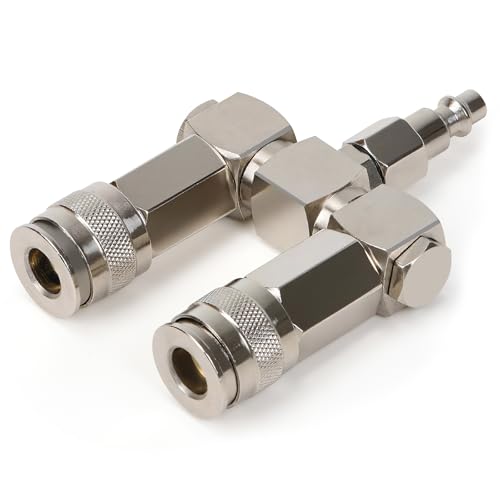 XAQMHSW 2-Way 1/4-Inch NPT Air Hose Splitter
|
7.8/10 | Buy |
FORNAX 2-Way 1/4-Inch NPT Air Manifold
This compact in-line splitter enables workshops to run two pneumatic tools simultaneously from a single air supply. Built with an aluminum body and steel quick-connect couplers, it offers a simple plug-and-play setup for routine shop tasks.
Pros
- Operates two air tools from one line
- Sturdy steel fittings on lightweight aluminum housing
- Compact footprint under 4 inches long
- Interchangeable with standard 1/4-inch NPT accessories
Cons
- Limited to two output connections
- Rigid straight design can be awkward in tight quarters
JASTIND 4-Piece Air Nozzle Blow Gun Kit
Built with an all-metal chrome body and an internally pressurized tapered nozzle, the JASTIND blow gun delivers concentrated airflow for clearing debris and dust. The included protective rubber tip prevents surface marring, making it well suited for workshop tasks and electronics cleaning.
Pros
- Durable chrome-plated alloy construction resists wear
- Protective rubber tip prevents scratches on workpieces
- Dual 1/4-inch connection options enhance tool versatility
- Tapered nozzle design easily reaches narrow gaps
Cons
- Requires manual Teflon tape wrapping to prevent air leaks
- Compact body provides limited reach in deep engine bays
LUMITECO 20-Inch Tire Inflator Hose Adapter
The LUMITECO 20-inch tire inflator hose adapter upgrades portable pumps and inflators with an extended nylon-wrapped rubber line, hands-free locking chuck, and integrated pressure release button. It is a practical upgrade for DIYers, motorists, and cyclists looking to service recessed valve stems without wrestling awkward twist-on fittings.
Pros
- 20-inch nylon-braided rubber extension provides significantly more maneuvering room around large wheel rims and tight spokes
- Built-in thumb-press air bleeder button makes dumping excess pressure fast and accurate without uncoupling the chuck
- 90-degree thumb-lock chuck creates an airtight seal that eliminates in-depth holding during tire filling
- Includes dedicated Presta valve adapter and converting nuts for broader vehicle and bicycle utility
Cons
- Open-flow chuck design will discharge air continuously if connected to an unvalved, live air line without an upstream trigger valve
- Features standard 0.305-inch x 32 TPI tire Schrader fine threads rather than standard workshop 1/4-inch NPT pipe threads
- Working pressure and burst pressure ratings are not explicitly stated in the manufacturer specifications
XAQMHSW 2-Way 1/4-Inch NPT Air Hose Splitter
Built for dual-tool setups, this nickel-plated steel manifold splits a single compressor line with full 360-degree swivel mobility to minimize hose tangles. It suits garage and workshop users operating standard pneumatic tools up to 300 PSI.
Pros
- Durable nickel-plated steel construction
- 360-degree swivel design prevents hose binding
- Universal coupler accepts multiple plug profiles
- Quick push-to-connect operation requires no tools
Cons
- Confined to standard 1/4-inch NPT connections
- Maximum working pressure capped at 300 PSI
- Simultaneous dual-tool use can reduce airflow volume
Connecting Dual Air Compressors: Plumbing, Calibration, and Safety
Running two air compressors simultaneously transforms modest garage machinery into a high-output pneumatic system. Instead of purchasing an expensive stationary unit, combining two portable machines delivers the air volume needed for painting and continuous grinding. Achieving this without equipment damage requires understanding pneumatic plumbing, pressure switch dynamics, and household electrical limits. Setting up a dual-compressor network involves straightforward steps, yet every fitting demands deliberate preparation to ensure safety and system longevity.
Why Connect Two Air Compressors in Parallel?
Pneumatic tools consume air volume measured in CFM rather than static tank pressure alone. While most single-stage compressors produce adequate pressure up to 135 PSI, their pumps often deliver only 2 to 4 CFM at 90 PSI. Connecting two units in parallel combines their individual output, allowing users to achieve 6 to 8 CFM or more at working pressure. This combined volume prevents continuous pressure drops when running air-hungry tools like dual-action sanders or framing nailers.
Tank buffer volume also expands significantly when linking two compressor reservoirs together. A single six-gallon tank depletes rapidly under sustained demand, forcing the pump motor to run constantly. Doubling the effective storage capacity creates a substantial pneumatic cushion that absorbs tool surges without triggering rapid motor cycling. Consequently, both compressor pump heads run cooler, which reduces mechanical wear on internal piston rings and valve plates.
Operating compressors in parallel differs fundamentally from connecting them in series. In a parallel arrangement, both pump discharges feed into a common line at matching working pressures, effectively doubling total volume flow. A series connection, where one compressor discharges into the intake of another, is unsafe because consumer units cannot handle pre-pressurized intake air. Parallel plumbing remains the standard method for safely increasing air volume in automotive garages and home workshops.
Electrical Circuit Requirements to Prevent Breaker Tripping
Electrical supply capacity represents the most frequent hurdle when configuring a dual-compressor workspace. Electric air compressor motors draw substantial running amperage, typically 10 to 14 amps on a standard 120-volt household circuit. More critically, electric motors pull a massive surge of inrush starting current that can briefly double or triple normal draw. Attempting to power two compressors from the same 15-amp or 20-amp circuit will trip the breaker as soon as both pumps engage.
To prevent breaker trips, you must plug each compressor into a completely separate branch circuit. This requires verifying that the chosen wall receptacles connect to different circuit breakers inside your panel. If your garage features only a single circuit, run a heavy-duty extension cord from an adjacent room or outdoor outlet. Always select a minimum 12-gauge or 10-gauge cord to prevent voltage drops that cause motor hum and thermal overload tripping.
Staggering the motor startup cycles provides an extra layer of protection against electrical spikes. Even when using independent circuits, preventing simultaneous starts reduces strain on your electrical service. Setting slight differences in cut-in pressure thresholds ensures one pump engages before the other rather than pulling heavy starting current at once. This staggered approach maintains continuous line pressure while keeping total garage electrical load manageable.
Pneumatic Plumbing Methods: Manifolds, T-Fittings, and Check Valves
Plumbing two compressors together requires a central junction point where both air lines merge before feeding downstream hoses. Heavy-duty splitters, such as the FORNAX 2-Way Straight Air Manifold Air Splitter or the steel 2-Way Air Hose Splitter, 1/4″ NPT Air Compressor connector, serve effectively as combiners when fitted with matching couplers. Instead of splitting one line to multiple tools, air flows from both tanks into the dual manifold ports and exits through a single discharge line. Solid brass tees with standard 1/4-inch NPT threads also create reliable, rigid junction points.
Integrating one-way check valves between each compressor tank and the combining manifold is a vital engineering practice. A check valve permits pressurized air to flow in only one direction, preventing air from one tank back-feeding into the other. Without check valves, if one unit runs at higher pressure or develops a valve leak, pressurized air rushes toward the lower-pressure pump. This back-feeding can damage factory unloader valves and cause unexpected venting through motor cowlings.
Coupler sizing and hose diameter dictate whether you actually benefit from doubled CFM capacity. Standard 1/4-inch quick-disconnect fittings create restrictive bottlenecks that cause dynamic friction loss under heavy airflow demands. Upgrading junction connections to 3/8-inch lines or high-flow couplers allows the merged air volume to travel unrestricted toward your pneumatic tools. Investing in high-flow hardware ensures that the combined output reaches your impact wrench or spray gun without substantial pressure drop.
Calibrating Pressure Switches and Regulators for Balanced Operation
Balancing the mechanical cut-in and cut-out pressure switches governs how effectively both machines share workload. Air compressors utilize pressure switches configured to stop pumping at a maximum cut-out pressure and restart at a lower cut-in threshold. If both switches are adjusted to identical settings, minor manufacturing tolerances mean one unit will inevitably trigger slightly ahead of the other. Understanding this mechanical behavior helps you configure the dual setup for either synchronized sharing or lead-lag operation.
In a lead-lag configuration, you establish one primary compressor and one secondary booster unit. The primary compressor has its cut-in threshold set higher, so it handles light-duty nailing and short air blasts independently. The secondary compressor has its cut-in pressure set slightly lower, engaging only when continuous tool draw pulls system pressure down further. This setup saves electricity during light tasks while retaining full dual-pump capacity for heavy workloads.
Discharge pressure regulation requires careful alignment at the tank manifolds. When joining two air lines into a single feed, you can either connect the un-regulated tank outlets directly into a shared downstream regulator, or set each individual tank regulator to the exact same output pressure. Utilizing a single downstream regulator mounted after the combining manifold generally yields the most stable results. A single master regulator prevents small differential fluctuations between factory gauges from causing erratic tool performance.
Step-by-Step Guide to Connecting Two Compressors Safely
Preparation begins by ensuring both air compressors are powered off and completely depressurized before assembling any fittings. Disconnect both machines from their wall outlets to eliminate any possibility of accidental motor engagement. Open the bottom tank drain valves and safety relief valves until tank pressure gauges read zero PSI. Working on pressurized fittings can result in high-velocity component ejection and severe personal injury, making complete depressurization an absolute safety rule.
Next, install high-quality pneumatic fittings using appropriate thread sealant on all threaded NPT joints. Wrap male threads with multiple layers of PTFE tape, wrapping clockwise in the direction of the threads to ensure a tight seal. Thread quick-connect plugs into the discharge ports of each compressor, and attach your check valves in line with the airflow direction pointing toward the central manifold. Tighten fittings securely with open-end wrenches, taking care not to over-torque brass threads and crack valve bodies.
Connect two independent air hoses from each compressor’s check-valve outlet into the dual inlet ports of your combining manifold. Keep these bridge hoses as short and wide as practical, preferably using 3/8-inch hoses to minimize internal friction. Connect your main tool supply hose to the single discharge outlet on the combining manifold. Double-check that all quick-disconnect sleeves are fully clicked forward into their locked positions to prevent accidental disconnects under pressure.
Power on the compressors one at a time to begin the initial pressurization and leak-testing sequence. Plug the first unit into its dedicated circuit, switch it on, and verify smooth pump operation until it builds partial pressure. Then plug the second unit into its independent circuit and turn it on, observing both tank pressure gauges as they climb toward cut-out thresholds. Apply a soapy water solution to every threaded joint and quick-connect collar, watching closely for bubbling that indicates escaping air.
Downstream Air Line Management and Tool Connections
Managing downstream air delivery ensures that the increased air volume reaches your pneumatic equipment cleanly and dryly. When two pumps run simultaneously, they generate substantial heat, which causes ambient moisture to vaporize and travel downstream into your hoses. Installing a combined moisture separator and particulate filter directly after the junction manifold traps water droplets before they reach spray guns or tools. Purging air lines with a versatile accessory like the 4PCS Air Nozzle Blow Gun Kit for Compressor clears residual debris and moisture before connecting delicate tools.
Tire service and vehicle maintenance benefit greatly from the increased air volume provided by paired compressors. Operating high-pressure inflators, such as the LUMITECO 20 Inch Tire Inflator Hose Adapter with its secure locking chuck, becomes fast and effortless with dual-tank reserves behind the line. Large truck, trailer, and tractor tires hold substantial volume that quickly exhausts small portable tanks, causing tedious waits between pump cycles. The combined CFM output keeps tire inflation lines pressurized, allowing rapid inflation without stalling out halfway through tire seating.
Hose management around the combining junction prevents tripping hazards and mechanical strain on fittings. Heavy manifolds resting directly on compressor console covers can vibrate loose over time or damage factory regulator stems. Support the junction manifold securely on a wall bracket or shop cart, allowing flexible whip hoses to absorb motor vibration. Swiveling connectors, like the rotating design found on heavy-duty steel splitters, reduce hose twisting and protect quick-connect seals from lateral stress.
Critical Safety Precautions and Maintenance Routines
Safety protocols must never be compromised when linking multiple pressurized air reservoirs together. Every compressor tank must retain its factory ASME-certified safety relief valve in fully functional working condition. Never attempt to plug, cap, or adjust a tank safety valve to accommodate the second compressor’s higher operating pressure. If either pressure switch fails to shut off motor power, the safety valve’s spring-loaded ring must be free to pop open and vent excess pressure before tank structural limits are exceeded.
Daily moisture draining remains twice as critical when operating two compressors in a tandem configuration. Because both pumps compress ambient air and condense atmospheric water vapor, both steel tanks will accumulate condensation in their lower chambers. Open the bottom drain valves on both tanks at the end of every work session, allowing trapped water and air pressure to purge completely. Neglecting this routine allows internal rust to compromise tank walls and sends corrosive moisture into downstream air tools.
Thermal management and duty cycles require active monitoring during extended workshop projects. Most consumer portable air compressors feature a 50 percent duty cycle rating, meaning they should rest as much time as they spend actively pumping. While dual compressors share the airflow burden, continuous heavy-demand operations like auto body sanding can still cause both motors to run hot. Monitor pump head temperatures, ensure cooling fans remain unobstructed, and allow both machines proper cool-down intervals to avoid tripping thermal overload switches.
Practical Takeaways for Workshop and Jobsite Operations
Connecting two air compressors together provides a cost-effective method for doubling pneumatic capacity without replacing your existing equipment. By pairing units through parallel plumbing, dedicated electrical circuits, and one-way check valves, you gain industrial-level air delivery while maintaining portability. When light framing or tire top-offs require simple mobility, you can instantly disconnect one compressor for travel while leaving the other in the workshop. This modular flexibility makes the dual-compressor configuration an exceptional setup for serious DIY enthusiasts and working tradespeople.
About the author
Tony Carrick is an experienced product researcher and writer specializing in tools, home improvement, automotive maintenance, and consumer equipment. With extensive experience reviewing tools and tackling hands-on renovation projects, he brings a buyer-focused perspective to compressor performance, usability, and overall value.