
How Does a Gas Powered Air Compressor Work: Practical Guide for 2026
Learn how does a gas powered air compressor work with this practical breakdown of engine mechanics, pilot valves, and air tanks for October 2026.
 By Tom Scalisi
Updated October 8, 2026
By Tom Scalisi
Updated October 8, 2026

Operating heavy pneumatic tools on remote jobsites or open agricultural land requires independent power that does not rely on electrical extension cords. Understanding how does a gas powered air compressor work reveals why these machines remain essential for framing crews, mobile service mechanics, and road maintenance teams. Instead of drawing current from a building circuit breaker, a gas compressor relies on an internal combustion engine to drive a mechanical pump, which compresses atmospheric air and stores it inside a steel reservoir. When selecting pneumatic gear for heavy tasks like running impact wrenches or multiple nailers, evaluating air compressor sizing for impact wrenches helps ensure the machine produces adequate volume for continuous work.
Gas-powered units differ fundamentally from electric garage models in how they regulate internal pressure, cool the pump head, and manage motor cycles. Because a gasoline engine cannot simply shut off and restart every few seconds as tools demand air, it utilizes specialized pilot unloader valves and automatic throttle regulators to manage pump output continuously. Proper operation also demands routine moisture management, making regular habits like draining moisture from an air compressor tank vital for preventing internal tank corrosion. Exploring the mechanical interaction between combustion engines, reciprocating pistons, and pneumatic safety valves clarifies how these versatile machines deliver reliable air volume under demanding conditions.
| Award | Product | ACR Score About ACR ScoreThe ACR Score is our own rating from 0 to 10, based on performance, design and build, ease of use, and value. It reflects independent research and is never influenced by manufacturers, retailers, or affiliate commissions. Learn more › | |
|---|---|---|---|
| Best Overall |
9 Gallon Twin-Tank Gas Powered Air Compressor
|
9.2/10 | Buy |
| Best Value |
 XtremepowerUS 13.0HP Horizontal Air Compressor
|
9.2/10 | Buy |
| Best Budget |
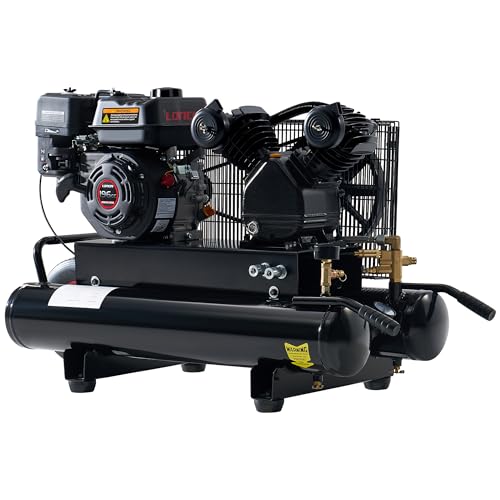 Albott 6.5HP Gas Powered Air Compressor 8 Gallon
|
9.1/10 | Buy |
 VEVOR 9 Gallon Twin-Tank Gas Powered Air
|
8.9/10 | Buy | |
| Best Premium |
 HPDMC 13HP Gas Powered Air Compressor, 3-Cylinder
|
8.8/10 | Buy |
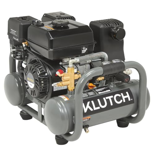 Klutch 4-Gallon Pontoon Air Compressor, 6.5 HP
|
8.6/10 | Buy | |
 VEVOR 13.2 Gallon Gas Powered Air Compressor
|
8.6/10 | Buy | |
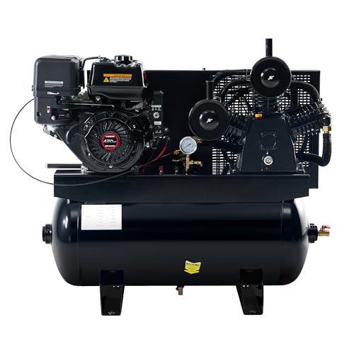 Albott 13HP Gas Air Compressor 30 Gallon
|
8.6/10 | Buy | |
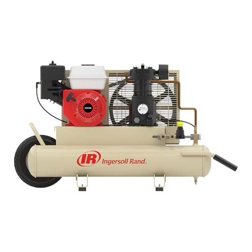 Ingersoll Rand SS3J5.5GH-WB 5.5 HP Gas Air
|
8.3/10 | Buy | |
 XtremepowerUS 13.0HP Air Compressor Tank 30 Gallon
|
8.0/10 | Buy |
The Mechanics and Operation of Gas Powered Air Compressors
A gas-powered air compressor converts the chemical energy stored in gasoline into mechanical kinetic energy, which is subsequently converted into stored pneumatic potential energy. At its core, the assembly couples an internal combustion engine to a positive-displacement reciprocating pump mounted atop a pressure vessel. Unlike standard electric units that cycle power to the motor when reaching maximum pressure, a gas unit operates on a continuous-run principle. The engine continues running while specialized pneumatic control valves regulate whether the pump compresses air or idles freely.
1. The Internal Combustion Engine: Generating Primary Mechanical Force
The primary power plant on a gas air compressor is a four-stroke overhead valve (OHV) gasoline engine. These engines typically range from small displacement motors generating around 5.5 to 6.5 horsepower up to larger commercial engines producing 13 horsepower or more. During the intake stroke, the engine draws an air-fuel mixture through the carburetor or fuel system into the combustion chamber. The compression and combustion strokes ignite this mixture via a spark plug, driving the piston downward to rotate the engine crankshaft.
Commercial-grade engines commonly incorporate low-oil shutdown sensors that automatically cut ignition if oil drops below safe operational thresholds. This safety measure protects the engine block from catastrophic seizure during uneven jobsite placement or long run periods on service trucks. Engine starting is handled either through a manual recoil pull-starter or an integrated electric starter wired to an external battery system. The rotational speed of the engine crankshaft, usually governed around 3,000 to 3,600 revolutions per minute under load, provides the primary mechanical drive force for the pneumatic assembly.
Fuel efficiency and tank capacity dictate continuous run duration on remote sites where refueling interrupts active work. Standard fuel tanks range from roughly 0.8 gallons on compact jobsite models to several gallons on stationary truck-mounted setups. Because gasoline engines produce exhaust gases containing carbon monoxide, these compressors must always operate outdoors in open, well-ventilated spaces. Storing fuel safely and maintaining clean carburetor jets prevents erratic engine surging that could destabilize air production.
2. The Drive System: Pulleys, Belts, and Pump Speed Reduction
Transferring mechanical energy from the engine crankshaft to the compressor pump requires a heavy-duty belt-drive configuration. While the engine operates at high rotational speeds, reciprocating compressor pumps function most reliably and generate less friction heat at much lower speeds, often between 800 and 1,200 revolutions per minute. A smaller drive pulley attached to the engine output shaft connects via reinforced V-belts to a substantially larger flywheel mounted on the compressor pump crankshaft. This diameter ratio creates mechanical gear reduction, trading high rotational velocity for increased torque.
The compressor flywheel serves a dual purpose beyond torque multiplication and rotational momentum smoothing. Manufacturers design the flywheel spokes as aerodynamic fan blades with extended directional fins. As the flywheel rotates alongside the pump, these integrated blades generate continuous high-velocity airflow directed across the pump cylinder heads and intercooling tubes. This forced air cooling dissipates intense thermal energy created during the rapid compression of atmospheric air.
Proper belt tension and alignment ensure maximum energy transfer without slippage, premature belt fraying, or excessive side-load bearing wear. An enclosed metal belt guard surrounds the moving pulleys and V-belts to protect operators from pinch points and shield the drive system from jobsite debris. Maintaining proper belt tension prevents power loss when the pump encounters higher backpressure inside the storage reservoir.
3. Reciprocating Piston Pump Mechanics: Suction and Compression
The compressor pump utilizes positive displacement pistons moving inside cast-iron cylinders to compress air molecules. As the pump crankshaft turns, connecting rods push one or more pistons through alternating downward and upward strokes. During the downward intake stroke, the piston creates a partial vacuum inside the cylinder bore. Atmospheric air passes through an intake air filter, which traps dust and abrasive particulates, and forces open flexible steel intake reed or disc valves to fill the cylinder chamber.
When the piston reaches bottom dead center and reverses upward, the increasing pressure inside the cylinder forces the intake reed valve tightly shut against its valve plate. As the piston rises toward top dead center, it traps the air volume and compresses it into a progressively smaller space. Once internal cylinder pressure exceeds the threshold holding the discharge valve closed, the compressed air forces the discharge valve open and exits the pump head through heavy-duty copper or aluminum discharge tubing.
Pumps are configured in single-stage or multi-cylinder two-stage designs depending on their maximum operating pressure. In a single-stage pump, each cylinder compresses air directly from atmospheric pressure to the final working pressure, typically between 115 and 135 PSI. In a two-stage pump, air is partially compressed in a larger low-pressure cylinder, routed through a finned copper intercooler tube to shed heat, and then compressed to higher pressures up to 175 or 180 PSI inside a smaller high-pressure cylinder. Heavy cast-iron construction and cast cylinder sleeves provide structural rigidity and wear resistance against continuous friction.
4. Continuous Run Regulation: Pilot Unloader Valves and Throttle Controls
The defining operational difference between electric and gas air compressors lies in their pressure regulation systems. Electric compressors utilize an electromechanical pressure switch that cuts electrical power to the motor when maximum cut-out pressure is reached. Repeatedly shutting off and restarting a combustion engine every few minutes would quickly destroy the starter, drain the battery, and create severe operational delays. Gas compressors solve this challenge by allowing the engine to run continuously while governing airflow pneumatically.
Regulation relies on a mechanical pilot valve connected directly to the air tank. When tank pressure rises to the preset cut-out limit, such as 125 or 135 PSI, the pilot valve actuates and redirects high-pressure air through small signal tubes to two critical components: the head unloader mechanism and the engine throttle control. At the pump head, the pneumatic signal actuates unloader plungers that hold open the intake valves or vents pump discharge air directly to atmosphere. With the intake valves held open, the pistons cycle freely without compressing air, eliminating pump mechanical resistance.
Simultaneously, the air signal travels to a pneumatic throttle control cylinder, often called a bullwhip, linked directly to the engine carburetor throttle arm. The air pressure extends a piston rod against a return spring, pulling the engine throttle back to low idle speed. The engine quietly idles and the pump spins without load, conserving fuel and reducing component wear. When pneumatic tools consume air and tank pressure drops to the preset cut-in threshold, the pilot valve closes and vents the control lines, releasing the throttle arm to accelerate the engine back to full operating speed while the unloader plungers retract to resume air compression.
5. Air Storage Vessels, Check Valves, and Tank Configurations
Compressed air leaving the pump travels through a high-temperature discharge tube directly toward the storage tank. Before entering the vessel, the air must pass through a heavy brass one-way tank check valve. This check valve contains an internal spring-loaded disc that opens easily under forward pressure from the pump but seals instantly against reverse flow. Without this valve, high-pressure air stored inside the tank would rush back into the pump cylinders when the unloader vents to atmosphere, stalling the engine or continuously leaking air.
Gas air compressors utilize varied tank configurations tailored to specific jobsite mobility requirements. Portable contractor models frequently employ a twin-tank wheelbarrow design, positioning two horizontal cylindrical tanks side-by-side to create a stable, low center of gravity. These tanks typically hold 8 to 9 gallons total, paired with a front wheel and dual handles for maneuvering across rough jobsite ground. Smaller pontoon designs offer 4-gallon capacities for compact truck transport, while larger stationary models utilize 30-gallon horizontal ASME-certified tanks designed to be permanently bolted into service truck beds or workshop floors.
The air tank functions as both an energy accumulator and a pulsation dampener. Because reciprocating pistons deliver air in discrete high-pressure pulses with every upward stroke, direct delivery to air tools would cause severe line pressure fluctuation. The storage tank absorbs these pulses and maintains a steady reserve buffer, allowing tools to operate smoothly. Larger tanks provide a vital cushion that prevents the engine from hunting rapidly between idle and full throttle during intermittent tool operation.
6. Pressure Regulation, Air Distribution, and Tool Delivery
Air stored inside the tank exists at maximum operating pressure, which is usually higher than the working pressure required by individual air tools. The compressor manifold incorporates an adjustable line pressure regulator that controls the final delivery pressure routed to the tool air hoses. Turning the regulator knob adjusts internal spring tension against a flexible diaphragm, restricting or expanding the internal orifice to maintain a stable output pressure regardless of fluctuating tank levels. Two separate pressure gauges display tank internal pressure and regulated working line pressure respectively.
Most commercial gas compressors feature dual 1/4-inch or 3/8-inch NPT quick-connect brass couplers mounted downstream of the regulator. This arrangement allows multiple crew members to operate pneumatic tools simultaneously from a single power source. When learning setting up an air compressor for nail guns on framing jobsites, regulating pressure between 70 and 120 PSI protects tool internal seals while ensuring nails drive cleanly through structural lumber. Matching tool air requirements measured in cubic feet per minute (CFM) to pump output prevents severe line pressure drops during rapid firing cycles.
Air delivery ratings directly reflect engine horsepower and pump displacement capacity. Compact 5.5 to 6.5 horsepower units typically generate between 9 and 12 CFM at 90 PSI, which easily supports two to four framing nailers or continuous tire inflation. Heavy 13 horsepower models deliver 18 to 44 CFM at 90 PSI, providing sufficient continuous volume for high-demand pneumatic tools such as heavy impact wrenches, paint sprayers, or sandblasting equipment. Ensuring air lines maintain adequate internal diameter minimizes friction losses over long hose runs across job sites.
7. Thermal Management, Condensation, and Preventative Maintenance
Compressing atmospheric air generates substantial thermal energy according to fundamental thermodynamic laws. As air molecules are forced into smaller volumes, temperature spikes rapidly inside the pump cylinder head. Cast-iron pump designs dissipate this thermal load through deep cooling fins cast across the cylinder barrels and cylinder heads. Multi-stage units also incorporate finned intercoolers that drop air temperatures between compression stages, reducing moisture vapor carrying capacity and improving volumetric efficiency.
As hot compressed air enters the cooler steel storage tank, water vapor naturally condenses out of the air stream and collects at the lowest point of the tank shell. If left unmanaged, this acidic moisture causes internal tank rust, compromises vessel structural integrity, and travels down air lines to corrode pneumatic tools. Operators must purge this collected moisture daily using the tank drain valve located on the underside of the vessel. Reviewing standard guidelines on emptying an air compressor tank after use reinforces the importance of depressurizing the system and expelling standing water before transport or seasonal storage.
Routine preventative maintenance preserves pump lifespan and guarantees safe jobsite operation. Operators should regularly inspect the oil sight glass on the pump crankcase, maintaining proper levels of non-detergent ISO 68 or ISO 100 compressor oil to prevent ring and bearing wear. Engine crankcase oil requires separate maintenance according to engine manufacturer guidelines. Testing the spring-loaded ring on the ASME safety relief valve ensures that the vessel will automatically vent stored air if the pilot unloader valve fails to disengage the pump at maximum rated pressure.
Understanding how combustion engines, belt drives, reciprocating pump pistons, and pneumatic pilot unloader controls coordinate clarifies how gas powered air compressors function. By combining independent fuel power with continuous-run mechanical regulation, these machines deliver sustained, high-volume air delivery wherever electrical utility connections remain unavailable. Regular maintenance of intake filters, check valves, engine oil, and tank drains ensures these heavy pneumatic systems operate safely and reliably across years of demanding field service.
About the author
Tom Scalisi brings more than two decades of experience in construction, building maintenance, contracting, and hands-on tool use. His practical understanding of power tools, automotive work, repairs, and jobsite equipment helps readers evaluate compressors based on real workloads rather than specifications alone.