
Can I Add a Tank to My Air Compressor? A Practical Guide for 2026
Learn how can i add a tank to my air compressor works in October 2026, including storage benefits, plumbing configurations, and duty cycle limits.
 By Tony Carrick
Updated October 7, 2026
By Tony Carrick
Updated October 7, 2026
Pneumatic sanders, paint sprayers, and high-demand impact wrenches frequently starve standard workshop compressors of air pressure during continuous operation. When line pressure plunges and the electric motor scrambles to keep up, many equipment owners wonder: can i add a tank to my air compressor to increase capacity? The short technical answer is yes, connecting a secondary receiver tank is mechanically feasible and provides a larger volume of pressurized air buffer. However, expanding your storage capacity fundamentally alters how the pump cycles, requiring careful attention to motor cooling, plumbing safety, and condensation management.
While adding a secondary air reservoir gives you a longer burst of sustained pressure before the pump kicks in, it does not magically increase your compressor’s delivery rate in cubic feet per minute (CFM). Understanding the mechanical relationship between storage volume, pump recovery time, and component duty cycle helps prevent premature motor burnout. Choosing proper hardware, such as brass manifold fittings, correctly rated safety relief valves, and dedicated tank drain valves, ensures the modified pneumatic system runs safely and reliably.
| Award | Product | ACR Score About ACR ScoreThe ACR Score is our own rating from 0 to 10, based on performance, design and build, ease of use, and value. It reflects independent research and is never influenced by manufacturers, retailers, or affiliate commissions. Learn more › | |
|---|---|---|---|
| Best Overall |
Hromee 5-Piece 1/4-Inch Drain Valve Kit
|
8.9/10 | Buy |
 CNRAQR 150 PSI 1.6-Gallon Air Compressor
|
8.3/10 | Buy | |
 QWORK 10-Inch Tank Drain Valve Kit
|
7.8/10 | Buy |
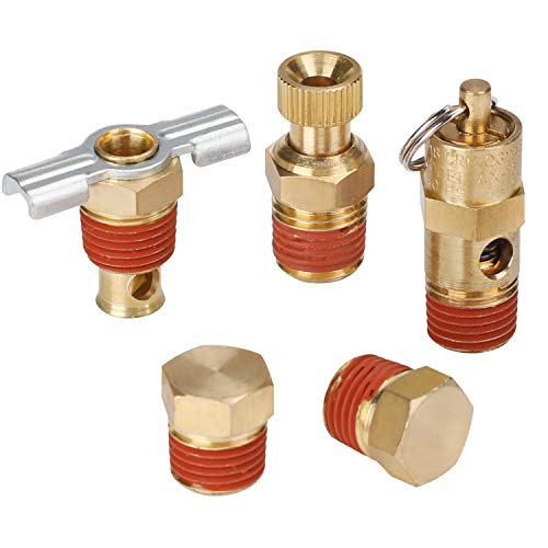
Hromee 5-Piece 1/4-Inch Drain Valve Kit
This brass fitting assortment provides essential replacement valves and plugs for routine compressor tank maintenance. It pairs winged and knurled drain petcocks with a 140 PSI safety relief valve for dependable pneumatic management.
Pros
- Solid brass body provides corrosion and heat resistance
- Two petcock styles offer flexible moisture draining options
- Integrated safety valve handles up to 55 SCFM flow
- Stainless steel relief components resist rust over time
Cons
- Requires separate thread sealant for proper sealing
- Safety valve maximum pressure is capped at 140 PSI
- Winged drain handle has a 12-pound torque limit
CNRAQR 150 PSI 1.6-Gallon Air Compressor
Built for onboard vehicle setups, this 12V system pairs a 150 PSI compressor with a 1.6-gallon aluminum tank to power air horns, suspension lifts, and tire inflation. Its IP54 weather rating and compact footprint make it a practical fit for trucks, trailers, and cars.
Pros
- Durable aluminum tank resists rust and corrosion
- Delivers up to 150 PSI working pressure
- IP54 rating shields against splashes and dust
- Compact design fits confined vehicle compartments
- Standard 1/4-inch NPT connection for versatility
Cons
- Small 1.6-gallon tank limits sustained air tool use
- IP54 rating provides splash resistance only, not submersion
- Adds over 12 pounds of onboard vehicle weight
QWORK 10-Inch Tank Drain Valve Kit
This braided steel extension kit simplifies tank draining by relocating hard-to-reach compressor valves. Rated up to 175 PSI and packaged with an adapter, it offers a reliable setup for standard workshop compressors.
Pros
- Corrosion-resistant braided steel construction
- Pre-applied sealant speeds up installation
- Includes adapter for 3/8-inch ports
- Handles up to 175 PSI reliably
Cons
- Fixed 10-inch length restricts mounting flexibility
- Not rated for high-pressure industrial systems
Expanding Air Storage: Technical Feasibility, Plumbing, and Operating Limits
Connecting an auxiliary receiver tank to an existing air compressor system is a viable way to expand stored air volume, but it fundamentally alters equipment cycling behavior. Many woodworkers and garage mechanics explore this upgrade after discovering that high-consumption tools quickly drain a compact factory tank. A secondary reservoir buffers against rapid pressure drop during brief, high-draw bursts, allowing tools like impact wrenches or framing nailers to run more smoothly. Nevertheless, an auxiliary tank does not increase pump displacement, meaning total recovery times will increase proportionally to the added volume.
Storage Volume Versus Pump Air Delivery
Pneumatic power systems rely on two distinct operating parameters: storage volume measured in gallons and continuous air volume delivery measured in cubic feet per minute (CFM). The storage tank acts solely as an air battery that holds pressurized energy until a tool releases it through the regulator. When you connect a secondary receiver, you expand the energy capacity of that battery, allowing you to operate high-draw tools for longer intervals before tank pressure drops below the working threshold. This buffer proves advantageous for intermittent applications, such as seating stubborn tire beads or running an impact wrench on suspension fasteners.
The primary performance limitation occurs when operators confuse storage volume with pump displacement. A compressor pump produces a fixed volume of air at a specific pressure, typically rated as CFM at 90 PSI, based on cylinder displacement and motor output. Adding another reservoir does not alter the displacement of the pump pistons or the speed of the motor. If a rotary sander or paint sprayer demands eight CFM continuously while the compressor pump produces only four CFM, the system will eventually run out of air regardless of tank size.
Compressor Duty Cycle and Motor Thermal Management
Every air compressor operates under an engineering specification known as duty cycle, which defines the allowable percentage of running time versus cooling time within a standard operating window. Consumer-grade oil-free compressors and compact jobsite units often feature a 50 percent duty cycle rating, meaning the pump should rest for just as long as it runs. Heavy-duty cast-iron stationary units typically tolerate higher duty cycles, sometimes reaching 75 to 100 percent under controlled ambient temperatures. Adding an auxiliary air tank forces the pump to run significantly longer during every recovery cycle, which directly challenges factory thermal limitations.
When a compressor refills a single five-gallon tank, the motor might run for two minutes before reaching the pressure switch cut-out threshold. Introducing a secondary five-gallon tank forces the pump to compress atmospheric air for roughly four continuous minutes to reach that same shut-off point. During prolonged compression cycles, heat builds rapidly within cylinder heads, piston seals, and motor windings. Oil-free pumps with PTFE piston sleeves are especially vulnerable to accelerated wear under sustained thermal stress, and repeated thermal overload tripping can permanently damage motor start windings.
Plumbing Configurations: Series Versus Parallel Piping
Connecting an auxiliary air tank requires choosing between two primary piping methods: series configuration or parallel configuration. In a parallel setup, the auxiliary tank connects directly to an unconstrained tank port on the primary compressor, effectively merging both vessels into a single large reservoir. Air flows freely between both tanks at all times, equalizing pressure across the entire storage system. The compressor pressure switch monitors the combined volume, cycling the motor on and off based on the unified pressure level of both tanks.
A series configuration positions the secondary tank downstream from the primary compressor manifold, often between the main tank and a distant tool drop. This arrangement can serve as a surge tank near remote workstations, isolating drop-line pressure fluctuations from the main compressor station. For most garage workshops, a parallel connection utilizing dedicated 1/4-inch or 3/8-inch NPT ports offers the most balanced performance. Connecting before the regulator ensures that both tanks store air at full cut-out pressure, maximizing the usable energy reserve for demanding tools.
Essential Pressure Vessel Safety Hardware
Safety must remain the primary consideration whenever you assemble or modify pressurized air systems. Compressed air represents stored potential energy that can cause catastrophic vessel failure if internal pressure exceeds structural thresholds. Any auxiliary vessel you add to your system must carry an official pressure rating that exceeds the maximum cut-out pressure of your compressor pump. Reputable air tanks typically feature ASME manufacturing certifications and stamped identification plates indicating maximum allowable working pressure, typically rated between 150 PSI and 200 PSI.
Every pressurized vessel in the circuit must have its own dedicated ASME-certified safety relief valve. Hardware kits such as the Hromee 5 Piece 1/4 Inch Compressor Air Tank Port kit provide vital safety components, including a brass 140 PSI safety valve designed to release excessive pressure automatically. Installing brass hex plugs and verified fittings ensures that every unused port on the auxiliary vessel remains tightly sealed against structural blowouts. A functional check valve must also protect the pump head from backpressure, allowing the unloader valve to depressurize the head during motor shutdown.
Managing Moisture Condensation Across Multiple Tanks
Compressing ambient air inevitably squeezes atmospheric water vapor out of suspension, causing liquid water to pool inside storage vessels. When you double your air storage capacity, you also double the volume of air compressed over time, leading to accelerated water accumulation. Moisture left sitting inside steel tanks causes internal oxidation, flaking rust particles that contaminate air tools, and eventual pinhole wall failure. An auxiliary vessel requires regular drainage attention to prevent internal corrosion and water carryover into downstream pneumatic lines.
Many factory air tanks come equipped with stiff, recessed needle petcocks that are difficult to reach and prone to seizing. Upgrading drain hardware with solutions like the QWORK Extended Tank Drain Valve Assembly Kit simplifies this daily maintenance chore. Featuring a 10-inch braided steel hose and brass adapter fittings rated up to 175 PSI, this type of extended assembly relocates the drain valve to an accessible exterior position. In addition, the Hromee 5 Piece 1/4 Inch Compressor Air Tank Port kit supplies winged drain cocks that facilitate quick manual purging after work sessions.
Vehicle-Mounted and Onboard Auxiliary Air Reservoirs
Auxiliary air tanks are not limited to stationary workshop environments; mobile repair trucks, off-road vehicles, and towing rigs frequently utilize secondary air storage. Onboard systems often integrate compact 12-volt compressors with dedicated aluminum reservoirs to operate air horns, suspension air bags, or tire inflation equipment. Systems such as the CNRAQR 150 PSI Air Compressor with 1.6 Gallon 200 PSI tank demonstrate how lightweight aluminum vessels provide corrosion-resistant air storage in harsh mobile conditions. Aluminum tanks resist exterior road exposure and eliminate internal rusting concerns common to budget steel vessels.
When plumbing an auxiliary tank into a vehicle or mobile trailer, vibration dampening and electrical circuit sizing become critical factors. The CNRAQR compressor platform incorporates an IP54 dust and splash protection rating, which helps maintain electrical reliability when mounted beneath a chassis or inside a utility truck bed. Auxiliary mobile tanks must be secured with grade-rated mounting brackets and flexible braided lines rather than rigid copper tubing to prevent fatigue cracking from road vibration. Ensuring all connections utilize quality thread sealant prevents parasitic air leaks that could cycle mobile compressors unexpectedly.
Step-by-Step Installation: Connecting a Secondary Storage Tank Safely
Installing an auxiliary air tank safely requires careful preparation, starting with complete depressurization of the existing compressor. Begin by disconnecting the compressor from its electrical power source to eliminate any risk of accidental motor startup. Open the existing tank drain valve and pull the manual ring on the ASME safety relief valve until line pressure gauges read zero PSI. Never attempt to unthread fittings, remove plugs, or connect plumbing lines while residual air pressure remains trapped inside the vessel.
Once the system is depressurized, identify a suitable unconstrained port on the primary compressor tank, typically a 1/4-inch or 3/8-inch female NPT bung. Clean all female threads with a wire brush to remove old pipe dope or debris before inserting new brass fittings. Apply quality thread sealing tape or liquid anaerobic thread sealant to male NPT threads, ensuring a leak-free seal that can withstand operating vibration. Thread a high-flow quick-disconnect coupler or a permanent brass tee fitting into the port, using smooth wrench torque to avoid stripping brass threads.
Connect the primary tank port to the auxiliary tank inlet using reinforced rubber air line, braided steel hose, or rigid copper tubing rated above the maximum cut-out pressure. On the auxiliary tank, install the mandatory safety hardware, including an ASME-certified safety relief valve on an upper port and a functional drain valve at the bottom. Once all plumbing connections are secured, close the drain valves, restore electrical power, and perform a soapy water bubble test across every joint at full cut-out pressure.
Pressure Switch Operation and Unloader Valve Dynamics
Many equipment owners mistakenly believe they need to adjust the compressor pressure switch when adding a secondary tank. In reality, factory pressure switch settings should generally remain untouched, as the cut-in and cut-out PSI thresholds reflect the design capabilities of the pump and motor. The switch operates based on internal pressure per square inch, not the total volume of air contained within the tanks. Whether the system holds three gallons or thirty gallons, the switch triggers cut-in and cut-out at the exact same internal PSI measurements.
Modifying factory pressure switch settings to achieve higher pressures can over-stress the electric motor and push the pump beyond its engineered thermal envelope. Furthermore, tampering with switch differentials can prevent the unloader valve from functioning properly. The unloader valve releases head pressure through a small tube whenever the pressure switch opens the electrical circuit. If head pressure is not completely purged because of improper plumbing or altered switch geometry, the electric motor will attempt to start against locked head pressure, triggering breaker trips.
Practical Verification and Final Operational Takeaways
Before putting a dual-tank air system into daily production, verify its real-world recovery time and observe motor running temperatures during continuous testing. Time the compressor as it recovers from standard cut-in pressure up to full cut-out pressure. The recovery duration will roughly double if you double your tank volume, which is completely normal. However, if the pump struggles to build final pressure or takes an excessive amount of time, check for restrictive interconnecting hoses or pump piston ring wear.
Evaluate whether the expanded air reserve genuinely resolves your pneumatic tool bottlenecks. If you operate brad nailers, tire chucks, or short-burst impact wrenches, the auxiliary tank provides a stable air supply that dramatically cuts down on annoying motor restarts. For continuous tools like sanders or spray equipment, recognize that the expanded tank only delays the inevitable pressure drop. When the secondary tank finally depletes, you must pause work to let the pump catch up and cool down properly.
Maintaining an expanded pneumatic system requires consistent daily habits and hardware checks. Drain both vessels after every working session using installed petcocks or extended drain assemblies to guard against hidden moisture corrosion. Inspect safety relief valves periodically by pulling their manual test rings while wearing eye protection to ensure internal springs remain free of debris. When executed with proper ASME-rated vessels, robust brass fittings, and respect for pump duty cycles, adding an auxiliary air tank delivers a practical, reliable storage upgrade for any workshop.
About the author
Tony Carrick is an experienced product researcher and writer specializing in tools, home improvement, automotive maintenance, and consumer equipment. With extensive experience reviewing tools and tackling hands-on renovation projects, he brings a buyer-focused perspective to compressor performance, usability, and overall value.