
How to Adjust Air Compressor Pressure Regulator: A Practical Guide for 2026
Master how to adjust air compressor pressure regulator valves for safe airflow and steady tool operation in October 2026.
 By Tom Scalisi
Updated October 13, 2026
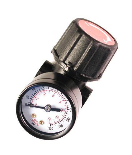
Operating pneumatic equipment with improper line pressure leads to premature tool wear, blown internal seals, and poor finish quality on workpieces. Dialing in the correct downstream line pressure ensures that pneumatic fasteners drive flush without splitting delicate trim molding, while impact wrenches receive sufficient force to break stubborn lug nuts free. Learning how to adjust air compressor pressure regulator assemblies gives you immediate control over working output rather than subjecting your air tools to full, unregulated tank capacity.
Most workshop setups feature either factory manifold knobs or dedicated in-line control units equipped with dual dials to monitor stored volume alongside working line pressure. If your delivery line suffers from sluggish airflow or unexpected leaks, reviewing our guide on replacing an air compressor hose can help isolate delivery restrictions before altering valve mechanisms. Understanding the mechanical interaction between internal regulator diaphragms, main control springs, and downstream air lines prevents erratic pressure fluctuations and keeps your pneumatic tools running smoothly across long work cycles.
| Award | Product | ACR Score About ACR ScoreThe ACR Score is our own rating from 0 to 10, based on performance, design and build, ease of use, and value. It reflects independent research and is never influenced by manufacturers, retailers, or affiliate commissions. Learn more › | |
|---|---|---|---|
| Best Overall |
Primefit CR1401G 1/4-Inch Air Regulator
|
9.1/10 | Buy |
 Hromee AW2000-02 1/4-Inch Filter Regulator |
8.1/10 | Buy | |
 THB 3/4-Inch NPT Air Pressure Regulator |
8.1/10 | Buy |
Primefit CR1401G 1/4-Inch Air Regulator
Designed for pneumatic setups requiring steady pressure control, the Primefit CR1401G delivers up to 60 SCFM at 100 PSI with a steel-shielded gauge for added durability. Its reversible mounting configuration accommodates different airflow directions, making it a practical replacement for standard 1/4-inch compressor lines.
Pros
- Accurate pressure regulation from 1 to 150 PSI
- Durable steel housing protects the pressure gauge
- High-flow capacity of 60 SCFM at 100 PSI
- Impact-resistant composite adjustment knob
Cons
- Must be oriented correctly for proper airflow direction
- Maximum inlet pressure is capped at 200 PSI
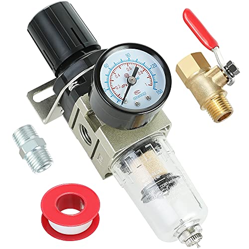
Hromee AW2000-02 1/4-Inch Filter Regulator
Designed for compact workspaces, this piggyback system integrates moisture filtration and pressure regulation into a single unit. Its brass filter element helps protect pneumatic tools from water and debris, while the included bracket and shutoff valve simplify setup.
Pros
- Durable brass filter element resists wear over time
- Dual-unit gauge provides clear pressure readings
- Compact piggyback design suits space-constrained setups
- Includes shutoff valve, bracket, and seal tape
Cons
- Requires manual operation to drain collected fluids
- Pressure capacity is capped at 150 PSI
THB 3/4-Inch NPT Air Pressure Regulator
Designed for high-demand pneumatic setups, this THB in-line regulator handles flow rates up to 140 SCFM with an adjustable output from 7 to 215 PSI. It includes an integrated pressure gauge and mounting bracket, making it well-suited for high-volume workshop air lines.
Pros
- High 140 SCFM airflow capacity for demanding tools
- Broad adjustable output range up to 215 PSI
- Comes complete with mounting bracket and pressure gauge
- Locking knob prevents accidental pressure drift
Cons
- Adjustment knob is composite rather than metal
- May require adapters for smaller air supply lines
- Provides pressure regulation without moisture or particulate filtration
Complete Guide to Adjusting and Calibrating an Air Compressor Pressure Regulator
Regulating air delivery is a fundamental step in operating any pneumatic system safely and efficiently. A properly calibrated regulator prevents tool damage, conserves compressed air, and guarantees consistent mechanical output across diverse shop applications. Balancing static and dynamic pressures eliminates frustrating performance drops while safeguarding sensitive pneumatic mechanisms from extreme tank pressure spikes.
The Difference Between Tank Pressure and Regulated Working Pressure
An air compressor storage tank holds compressed air at elevated cut-out pressures, often between 125 and 175 PSI. This internal volume acts as an energy buffer, allowing pneumatic tools to run without forcing the pump motor to cycle constantly. However, standard handheld pneumatic tools cannot tolerate raw, unmanaged tank pressures. Subjecting brad nailers, paint sprayers, or impact wrenches directly to maximum tank pressure quickly ruptures internal seals, blows out O-rings, and creates serious workshop hazards.
The pressure regulator serves as a mechanical control valve positioned between the air storage tank and the delivery hose. It functions through an internal diaphragm balanced against an adjustable spring, throttling airflow to maintain steady downstream pressure regardless of tank level. While the compressor pressure switch dictates when the pump motor starts and stops, the regulator strictly controls output pressure feeding your tools. Reviewing a two-stage vs one-stage air compressor comparison clarifies how higher storage pressures still rely on downstream regulation for tool safety.
Essential Safety Precautions Before Making Adjustments
Safety must remain the top priority before adjusting any pressurized pneumatic hardware in your workspace. Always wear safety glasses when handling air lines, regulator knobs, and manifold fittings, as pressurized air can dislodge fine grit or metallic debris. Inspect the ASME safety relief valve ring on the compressor tank to confirm it operates freely without sticking. Never attempt to adjust an air regulator by forcing a stuck or seized control knob, as cracked composite housings can suddenly fail under pressure.
Check your air hoses and quick-connect couplers for signs of outer casing damage, bulges, or loose crimps before pressurizing the delivery line. A damaged hose subjected to rapid pressure increases can whip violently or rupture without warning. Ensure that all downstream tools are safely disconnected before you alter regulator knob settings. Taking these precautions protects both your workshop equipment and your personal safety while setting up working pressures.
Step-by-Step Procedure for Adjusting the Pressure Regulator Knob
Begin by allowing your compressor pump to run uninterrupted until it reaches its standard cut-out threshold and the motor shuts off. Observe the tank pressure gauge on the manifold to confirm that the storage cylinder is adequately pressurized and that the pressure switch functions normally. Locate the regulator control knob situated adjacent to the regulated working line gauge. Most contemporary regulators utilize a locking composite knob that must be pulled outward or upward with a noticeable click to unlock the adjustment mechanism.
To reduce output pressure, turn the adjustment knob counterclockwise to loosen internal spring tension against the diaphragm. If the delivery line is completely closed and holds pressurized air, turning the knob counterclockwise will not immediately drop the gauge needle. You must vent a burst of air from the downstream line or coupler to relieve trapped line pressure and let the gauge reflect the lower setting. Once the gauge drops below your desired target, you can prepare to adjust upward toward your final operating pressure.
To increase working pressure, turn the adjustment knob clockwise to compress the internal control spring. As you rotate the knob clockwise, watch the regulated pressure gauge dial climb steadily toward your target number. It is best practice to always adjust upward to your final target number rather than downward, because mechanical springs seat more consistently under increasing tension. Once the gauge needle rests precisely on your target pressure, push the knob inward until it clicks firmly into its locked position to prevent vibration drift.
For replacement components like the Primefit CR1401G Replacement Air Regulator, which features a steel-protected gauge and an accurate regulation range between 1 and 150 PSI, setting pressure requires gentle knob movements. The high-impact composite knob provides responsive tactile feedback, but forcing the mechanism past its mechanical stops can damage internal threads. Rely on steady, incremental turns while watching the gauge needle settle to avoid overshooting your pneumatic tool operating range.
Dynamic Versus Static Pressure: Compensating for Line Drop
Static pressure is the reading displayed on your regulator gauge when the downstream air line is completely closed and no air is flowing. Many operators set their regulator to 90 PSI while the tool is idle and assume the tool will receive that exact pressure during use. However, as soon as you trigger a continuous air tool like a paint sprayer or die grinder, dynamic pressure loss occurs. Air rushing through fittings, narrow couplers, and long hoses creates frictional drag that causes active line pressure to drop significantly below the static reading.
To properly calibrate your regulator for demanding tools, adjust the knob while the tool is actively cycling under test conditions. Connect your tool, trigger it to discharge air freely, and observe how far the regulated pressure needle dips on the dial. If your 90 PSI static setting drops to 75 PSI during continuous trigger engagement, turn the regulator knob clockwise while the tool is running until the needle maintains 90 PSI under active airflow. This dynamic adjustment ensures that the pneumatic motor receives adequate force to maintain peak operating speed without stalling.
Air hose internal diameter plays a substantial role in how severe this dynamic pressure drop becomes during demanding tasks. Standard 1/4-inch hoses introduce significant flow restriction over distances beyond twenty-five feet, choking high-draw tools regardless of your regulator setting. Upgrading to a 3/8-inch internal diameter hose significantly reduces frictional flow resistance and stabilizes working pressure at the tool inlet. Compensating for friction losses through dynamic adjustment prevents frustrating motor stalls and guarantees repeatable fastener drive depth in dense materials.
Incorporating Air Filtration and Moisture Separation
Clean and moisture-free air is just as crucial as accurate line pressure when operating precision pneumatic equipment. Ambient air drawn into an air compressor contains atmospheric humidity that condenses into liquid water inside the storage tank during compression. If this moisture travels downstream past the regulator, it washes away factory lubricants inside air tools, causes internal corrosion, and ruins paint finishes. Combining your regulator with a dedicated moisture separator creates an effective defense against liquid contamination.
Units such as the Hromee 1/4 Inch Air Compressor Filter Regulator offer a practical piggyback configuration that merges filtration and pressure control into a compact assembly. This unit utilizes a porous brass filter element to trap fine particulate debris and liquid water before air reaches the regulator seat, prolonging diaphragm life. The transparent filter cup allows you to visually inspect collected moisture and oil volume, while an integrated manual drain lets you purge contaminants rapidly. Incorporating a brass shutoff ball valve right at the regulator bracket gives you instant manual control over line isolation during maintenance.
Moisture separation at the regulator cannot replace routine maintenance at the storage tank itself. In addition to using inline filtration, maintaining your system requires regular tank drainage, and following practical guidance on replacing an air compressor drain valve helps resolve stuck petcocks that trap corrosive water. Combining clean tank management with an inline brass filter regulator ensures that downstream air remains dry, cool, and regulated to the exact pressure required for fine finishing work.
Port Sizing, Airflow Direction, and Flow Capacity Restrictions
Air pressure regulators are strictly directional devices and must be installed according to the airflow direction marked on the housing. Most regulator bodies feature an embossed arrow indicating the required path from the inlet port connected to the compressor toward the outlet port connected to the delivery line. Installing a regulator in reverse causes severe air leaks, prevents proper pressure throttling, and can pin the gauge needle at maximum tank pressure regardless of knob adjustments.
Certain models accommodate flexible orientation depending on how you arrange your workspace manifold. For example, the Primefit CR1401G Replacement Air Regulator is engineered for right-to-left airflow when configured with its adjustment knob facing upward, but it can be mounted with the knob downward to accommodate left-to-right flow. Understanding this configuration requirement ensures that the internal valve seats properly against incoming air pressure, preserving regulation accuracy up to its 150 PSI maximum output rating.
Port sizing and CFM flow ratings must also align with your tool consumption needs to avoid massive delivery bottlenecks. While small trim nailers perform reliably through standard 1/4-inch NPT ports rated for 60 SCFM at 100 PSI, larger workshop piping networks require substantially greater volume. Heavy-duty options like the HEAVY DUTY IN-LINE COMPRESSED AIR PRESSURE regulator from THB utilize 3/4-inch female NPT ports and support high flow rates up to 140 SCFM. With a maximum input pressure of 250 PSI and adjustable output from 7 to 215 PSI, such high-capacity regulators prevent line choking across multiple simultaneous air drops.
Diagnosing Regulator Creep, Pressure Drift, and Valve Leaks
Pressure creep is one of the most hazardous malfunctions that can develop within an aging air compressor pressure regulator. Creep occurs when downstream pressure slowly climbs past your dialed setting while the delivery line is completely closed and idle. If you set your regulator to 80 PSI and return an hour later to find the gauge reading 120 PSI, your regulator is suffering from creep. This condition usually results from microscopic pipe scale, rust flakes, or hardened oil gumming up the internal valve seat, preventing the poppet from sealing completely.
A regulator exhibiting persistent pressure creep must be cleaned or replaced immediately to protect downstream tools from overpressurization. Disconnect the air supply, depressurize the manifold completely, and unthread the regulator bonnet to inspect the internal seat and rubber diaphragm. If the diaphragm shows visible tears, cracking, or hardening, it can no longer balance spring pressure against air flow and will cause erratic fluctuations. Cleaning the brass valve seat with a mild solvent and clean lint-free cloth often restores a positive seal if the elastomer components remain pliable.
External air leaks around the adjustment knob or bonnet threads indicate diaphragm blow-by or loose casing fasteners. If air audibly hisses from the regulator vent hole whenever the tank is pressurized, the internal diaphragm has likely ruptured. While high-impact locking composite knobs withstand standard shop wear, overtightening the knob past its limit can strip internal adjustment threads and cause the spring to slip. Replacing a worn regulator with a quality replacement unit restores reliable pressure containment and ensures accurate dial calibration.
Matching Working Pressure to Specific Pneumatic Applications
Every pneumatic tool is engineered to operate within a specific pressure band determined by its internal cylinder volume and mechanical design. Operating tools outside these manufacturer guidelines leads to premature mechanical failure, inaccurate results, and wasted energy. Light-duty pneumatic brad nailers and pin nailers typically require between 60 and 90 PSI to sink brads flush without blowing through thin veneer. Applying excessive pressure to finishing nailers accelerates bumper wear, breaks drive pins, and leaves unsightly indentations across the face of the workpiece.
Framing nailers and pneumatic staplers operate effectively between 90 and 110 PSI to consistently penetrate structural lumber and subfloor panels. Heavy-duty automotive air tools such as half-inch impact wrenches and pneumatic ratchets generally require 90 PSI measured at the tool inlet to produce their rated breakaway torque. Spray guns and delicate HVLP finishing systems often demand much lower regulated pressures, typically between 20 and 40 PSI at the regulator, to achieve fine atomization without creating severe overspray. Matching your regulator dial directly to the tool manufacturer specification ensures maximum efficiency and extends tool life.
Practical Verification and Routine System Care
Establishing a simple verification habit every time you power up your air compressor ensures long-term calibration consistency. Before connecting your primary tools, glance at both the tank gauge and the regulated line gauge to confirm that neither needle exhibits unexpected flutter or drift. Cycle the adjustment knob through a small adjustment arc and lock it back into position to keep the mechanical threads free from dust buildup and seized debris. Periodically check fittings with a mild soap-and-water solution to identify small micro-leaks around NPT thread connections.
Maintaining proper regulated line pressure ultimately protects your investment in pneumatic equipment while optimizing shop productivity. By understanding how to balance spring tension against line demand, compensating for dynamic friction drop, and incorporating clean filtration, you maintain full command over your compressed air delivery. With a properly dialed regulator, your tools deliver smooth, predictable power from the first fastener of the morning to the final spray pass of the day.
About the author
Tom Scalisi brings more than two decades of experience in construction, building maintenance, contracting, and hands-on tool use. His practical understanding of power tools, automotive work, repairs, and jobsite equipment helps readers evaluate compressors based on real workloads rather than specifications alone.