
How to Keep Moisture out of Air Compressor Tank: Practical Guide for 2026
Learn how to keep moisture out of air compressor tank techniques to protect your pneumatic tools and prevent tank rust with reliable workshop air drying strategies in October 2026.
 By Tom Scalisi
Updated October 8, 2026
By Tom Scalisi
Updated October 8, 2026
Compressed air systems naturally generate significant heat during operation, drawing ambient humidity straight into the pump cylinders where water vapor condenses into liquid inside the receiver. When liquid water pools along the bottom of a steel tank, it accelerates internal rust, contaminates pneumatic supply lines, and causes downstream air tools to sputter or corrode prematurely. Understanding how to keep moisture out of air compressor tank systems is essential for anyone operating paint sprayers, nail guns, plasma cutters, or automotive impact wrenches. Maintaining clean, dry compressed air protects costly equipment investments and guarantees consistent tool performance across demanding workshop projects.
While basic thermodynamic physics makes condensation unavoidable whenever air is compressed and cooled, practical workshop configurations use proactive moisture mitigation strategies. Combining regular tank purges, smart intake ventilation, rigid sloped piping, and high-efficiency particulate separators keeps moisture levels under strict control. Modern particulate traps and compact inline drying units capture residual water droplets before they can compromise sensitive pneumatic machinery. Applying these proven moisture management techniques ensures your air delivery system stays clean, dry, and dependable throughout daily operations.
| Award | Product | ACR Score About ACR ScoreThe ACR Score is our own rating from 0 to 10, based on performance, design and build, ease of use, and value. It reflects independent research and is never influenced by manufacturers, retailers, or affiliate commissions. Learn more › | |
|---|---|---|---|
| Best Overall |
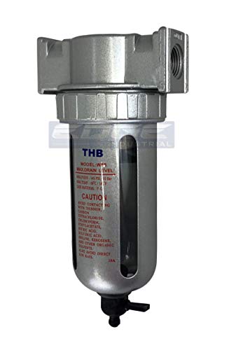
1/2" Particulate filter water trap seperator
|
9.1/10 | Buy |
| Best Value |
 LE LEMATEC Inline Air Compressor Water Separator
|
8.3/10 | Buy |
Complete Guide on Managing and Preventing Air Compressor Moisture
Managing moisture in a pneumatic system requires understanding the mechanical reality of how air compression interacts with ambient environmental humidity. Ambient air always carries a measurable percentage of suspended water vapor that cannot be completely blocked by a standard intake filter. When a compressor pump draws this humid air in and packs it into a rigid steel reservoir, the physical properties of the air change drastically. Addressing this moisture involves a coordinated defense that tackles ambient intake conditions, storage tank drainage routines, mainline distribution plumbing, and secondary point-of-use filtration.
The Thermodynamics of Tank Condensation
Every atmospheric air charge drawn into a compressor pump contains invisible moisture in the form of water vapor. As the pump compresses that ambient air to standard working pressures like 90 to 175 PSI, it forces air molecules into a fraction of their original volume. This rapid mechanical compression generates intense thermal energy, allowing hot compressed air to retain a high volume of water vapor while traveling through the pump manifold. Once that heated air enters the larger volume of the steel receiver tank, the metal tank walls act as a heat exchanger, rapidly cooling the compressed air charge.
Cool air cannot hold as much moisture as hot air, which causes the relative humidity inside the vessel to spike past its saturation dew point. Once the dew point is exceeded, the suspended water vapor converts into liquid water droplets through natural condensation. These droplets accumulate on the internal walls of the vessel and trickle down under gravity to settle at the lowest point of the tank floor. This mechanical reaction means the storage tank actually serves an intentional engineering role as the initial bulk moisture separator in your pneumatic circuit.
Allowing condensed water to pool indefinitely inside a steel tank creates serious mechanical and safety hazards. Water combined with compressed oxygen accelerates the formation of iron oxide, leading to internal tank flaking, pitted metal, and structural wall thinning over time. Loose rust particles circulate through the bottom manifold, quickly clogging check valves, regulator seats, and drain valve orifices. Accumulated water also reduces the effective air storage volume inside the reservoir, forcing the compressor motor to cycle more frequently to sustain operating pressure.
Establishing an Effective Tank Drainage Routine
The single most critical maintenance task for controlling reservoir moisture is establishing a consistent tank draining schedule. Liquid water must be purged from the receiver floor before it can stand long enough to initiate rust scale or get drawn into the discharge port. For hobbyists and occasional DIY users, draining the tank at the conclusion of every work session provides sufficient protection against standing liquid. For commercial workshops and high-duty-cycle production environments, purging the receiver at least once daily or between work shifts is recommended.
Executing a proper manual tank drain requires following clear depressurization and safety steps to avoid personal injury or valve damage. Begin by disconnecting the compressor from electrical power to prevent the motor from cycling unexpectedly during the procedure. Reduce the internal tank pressure to a moderate level, typically between 10 and 20 PSI, using an air blow gun or regulator relief. Draining a tank under maximum pressure can blast rust scale violently across the workshop floor and damage the rubber seals inside the drain valve mechanism.
Place a shallow catch basin or cloth rag beneath the bottom drain port to capture the ejected fluid, which often carries an oily, rust-tinted residue. Slowly turn the drain valve counterclockwise until you hear air escaping and observe liquid discharging into the container. Allow the valve to remain open until all spitting moisture stops and only clean, dry air escapes from the fitting. Once the vessel is completely empty of moisture and remaining pressure, close the valve firmly by hand without overtightening the fitting.
Upgrading Drain Hardware for Simplified Maintenance
Many factory air compressors ship with inexpensive threaded needle petcocks or miniature thumb valves installed at the bottom bung. These miniature brass petcocks feature tiny internal passages that easily become clogged with dislodged rust scale and dried pump oil sludge. Their tight clearance and stiff knurled knobs often make them awkward to reach beneath low-clearance horizontal or pancake tanks. When drain valves are difficult or uncomfortable to operate, users frequently skip daily draining, allowing destructive water pools to linger for weeks or months.
Replacing a restrictive petcock with an extended quarter-turn brass ball valve dramatically improves maintenance compliance and purging efficiency. A quarter-turn ball valve features a full-port internal opening that allows liquid water and loose sediment to flush out instantly without bottlenecking. Adding a brass street elbow and an extended pipe nipple positions the valve lever out toward the front edge of the tank base. This accessible mechanical extension allows you to drain the reservoir in seconds without tipping the machine or scraping your knuckles against frame brackets.
Workshops seeking automated moisture removal can install electronic timed solenoid drain valves or mechanical float drains. An electronic timer valve utilizes an adjustable digital controller that opens a motorized solenoid port for a few seconds at pre-set hourly intervals. Alternatively, pneumatic systems utilizing dedicated filtration bowls can take advantage of semi-automatic overnight discharge mechanisms. When the pneumatic line remains pressurized under active operation, the valve holds the collected fluid securely inside the reservoir, but as soon as system pressure drops to zero at the end of the day, the internal spring mechanism automatically releases the trapped liquid.
Controlling Ambient Intake Air Conditions
While you cannot alter the laws of gas compression, you can dramatically influence how much water vapor enters the pump by optimizing the intake environment. Air compressors draw their supply directly from the surrounding ambient space, meaning high-humidity locations introduce massive amounts of water into the compression chamber. Placing an air compressor in a damp basement, unconditioned outdoor shed, or directly beside a steam-generating washing bay forces the unit to compress moisture-heavy air constantly. Shifting the machine to a cool, dry, and well-ventilated location substantially reduces baseline condensation.
Intake air temperature plays an equally important role in overall moisture accumulation during extended running cycles. Cooler air holds less total moisture by volume than warm summer air, creating a lower relative humidity ratio before compression begins. Some workshop owners run rigid intake piping from the compressor head through an exterior wall to pull cool air from a shaded, dry outdoor perimeter. If extending the intake line, ensure the pipe diameter is stepped up appropriately to prevent intake air restriction, which can cause the pump cylinders to starve and overheat.
Installing a standalone dehumidifier inside an enclosed garage workshop provides measurable moisture reduction benefits for pneumatic tools. Lowering the ambient relative humidity of the room to 40 or 50 percent directly decreases the vapor volume drawn into the compressor pump. Maintaining a climate-controlled workspace also prevents rapid temperature swings between daytime warmth and nighttime drops. Extreme temperature swings cause rapid condensation on cold metal tools, exposed airline surfaces, and tank walls alike.
Mainline Particulate Filters and Bulk Water Traps
Purging the compressor tank regularly protects the steel vessel, but it does not prevent microscopic water vapor from traveling down the discharge line. Air leaving the tank remains warm and saturated, carrying fine atomized liquid droplets along the hose towards your pneumatic tools. Installing a dedicated particulate filter and water separator directly downstream from the compressor manifold provides the necessary second tier of moisture filtration. These units utilize internal centrifugal baffles to spin incoming air, throwing heavy liquid droplets and solid contaminants outward against the bowl walls where they drain to the bottom.
A high-capacity bulk separator, such as the 1/2″ Particulate filter water trap seperator, provides heavy-duty filtration capacity suitable for workshop headers. This unit features a 5-micron filter element capable of removing up to 95 percent of liquid moisture droplets and suspended debris from the passing airflow. With an input rating up to 175 PSI, a maximum output rating of 145 PSI, and a substantial 106 CFM flow rate, it accommodates high-demand pneumatic setups without choking airflow. Its generous 5-ounce polycarbonate bowl is protected by an outer metal guard to withstand accidental impacts in active shop environments.
Bulk separators also incorporate integrated drain mechanisms to simplify the removal of captured moisture without requiring system teardowns. The THB unit includes a semi-automatic drain that functions effectively as an overnight drain during shop downtime. While the line maintains active operating pressure, the internal drain valve remains closed to prevent air leakage, but as soon as the line depressurizes, the valve opens automatically to eject trapped fluids. Users can also manually discharge the 5-ounce bowl at any point during active operations by depressing the bottom drain pin.
Workshop Air Piping Layouts and Moisture Drop Legs
The layout and physical geometry of your workshop air distribution plumbing have a massive impact on whether moisture reaches your pneumatic tools. Running a short rubber whip line straight from the compressor discharge into a tool guarantees that hot, moist air enters the tool mechanism before it has time to cool and condense. To capture moisture effectively, compressed air needs sufficient linear travel distance through metal piping to cool down below its dew point. Installing rigid aluminum or copper piping along the workshop wall allows heat dissipation before the air reaches final drop stations.
Professional pneumatic plumbing relies on deliberate slope angles and vertical drop legs to isolate condensed water using gravity. The main overhead header pipe should always pitch gently downward, sloping approximately one inch for every ten feet of horizontal run away from the compressor pump. At the lowest end of the sloped run, install a dedicated vertical drain leg equipped with a manual ball valve to catch condensation moving along the bottom of the pipe. When routing secondary air drops down to workbenches, always take the connection off the top of the main header using a tee fitting pointed upward.
Taking air off the top of the header in an inverted U-shape loop ensures that liquid water running along the bottom of the pipe cannot spill into your tool drop. Each vertical workbench drop should extend downward past the tool coupler to form a dirt and moisture leg at the base. Installing a reliable particulate filter and drain valve at the bottom of each vertical drop leg creates a reliable zone for collecting condensation. Avoid using PVC or CPVC plastic pipe for compressed air distribution, as brittle plastic cannot safely handle pressure spikes and can shatter into dangerous flying shards.
Point-of-Use Inline Filters for Sensitive Applications
Certain pneumatic tasks have zero tolerance for even trace amounts of moisture, requiring dedicated point-of-use filtration right at the tool inlet. Automotive spray painting is notoriously vulnerable to moisture contamination, where microscopic water droplets cause blistering, pinholes, and unsightly fish-eye craters in fresh clear coats. Plasma cutting systems and fine air sanders also suffer accelerated consumable wear, electrode oxidation, and erratic arc stability when powered by wet air. For these exacting tasks, attaching a compact inline filter directly ahead of the tool handle provides essential final-stage insurance.
A dedicated tool-mounted unit, such as the LE LEMATEC Inline Air Compressor Water Separator, delivers targeted protection without adding cumbersome bulk. Featuring an ultra-slim 2.94-inch profile and a lightweight 4.2-ounce body, this AI-304 model threads directly onto standard 1/4-inch NPT tool inlets without causing severe hand fatigue or altering your spray aim. Unlike fragile plastic housings that risk cracking under pressure spikes, its reinforced aluminum alloy body carries an industrial rating up to 200 PSI. This sturdy construction creates a durable physical barrier that safely traps water droplets and oil particles before they can enter sensitive tool valves.
Point-of-use units rely on specialized internal elements, such as sintered bronze filters, to separate liquid moisture, fine particulate dust, and stray compressor oil from the airflow. The impact-resistant polycarbonate bowl on the LE LEMATEC separator lets you visually monitor water accumulation while you work. When the small reservoir fills, a quick-action push-button drain valve allows you to vent trapped waste instantly without unscrewing fittings or bleeding system air pressure. Pairing a high-flow bulk mainline trap with an agile point-of-use inline separator creates a comprehensive defense system that eliminates moisture-related project defects.
Long-Term Tank Integrity and Maintenance Protocols
Consistently keeping moisture out of your air compressor tank does more than deliver dry air to your nailers and sprayers; it preserves structural safety. Steel pressure vessels are subjected to cyclical expansion and contraction stress during every cut-in and cut-out compression sequence. When chronic internal standing water causes undetected rust pitting along the bottom weld seams, the pressure vessel loses structural thickness and integrity. Regularly inspecting the external underside of the tank for paint bubbling, rust weeping, or visible corrosion helps you catch early warning signs of internal degradation.
Safety maintenance also requires verifying the proper operation of the ASME safety relief valve installed near the compressor pressure switch. Once every few months, gently pull the metal ring on the safety valve while the tank holds low pressure to verify the spring-loaded plunger moves freely without sticking. If the valve seat is jammed with rust debris or dried oil residue, replace it immediately with a factory-specified safety relief component. Always disconnect the power cord and bleed all stored air pressure completely before attempting to unthread any tank fittings, drain hardware, or manifold accessories.
Managing moisture in your compressed air system is an ongoing maintenance discipline rather than a single hardware installation. By pairing daily tank drainage with accessible quarter-turn valves, controlling ambient intake humidity, utilizing sloped overhead piping, and installing multi-stage filtration units, you create a robust moisture-free pneumatic environment. This systematic approach ensures your compressor receiver stays structurally sound while your pneumatic tools deliver smooth, dry, and dependable power across years of demanding workshop use.
About the author
Tom Scalisi brings more than two decades of experience in construction, building maintenance, contracting, and hands-on tool use. His practical understanding of power tools, automotive work, repairs, and jobsite equipment helps readers evaluate compressors based on real workloads rather than specifications alone.