
How to Prevent Moisture in Air Compressor: Practical Guide for 2026
Learn how to prevent moisture in air compressor lines using effective water separators, desiccant dryers, and smart piping layouts in October 2026.
 By Bob Beacham
Updated October 8, 2026
By Bob Beacham
Updated October 8, 2026

Water spraying out of an HVLP paint gun or pooling inside an air tool will quickly ruin a finish and corrode precision internal components. When atmospheric air is squeezed into an air receiver tank, the heat of compression forces water vapor into suspension until the air cools and deposits liquid condensation inside your tank and air lines. Learning how to prevent moisture in air compressor setups is essential for anyone running pneumatic equipment, automotive paint sprayers, or plasma cutters. Taking control of humidity requires addressing condensation at every stage of the compressed air delivery path rather than relying on a single quick fix.
Standard workshop setups often struggle with liquid water because standard receiver tanks act as natural collection points without actively removing moisture from downstream lines. Combining proper tank maintenance with dedicated water separators, coalescing filters, and desiccant dryers creates a dependable barrier against line contamination. Implementing the right moisture management strategy keeps your pneumatic tools running smoothly and prevents costly defects on finished projects. By analyzing filtration options and delivery geometry, you can build a dry air system tailored to your garage or workshop demands.
| Award | Product | ACR Score About ACR ScoreThe ACR Score is our own rating from 0 to 10, based on performance, design and build, ease of use, and value. It reflects independent research and is never influenced by manufacturers, retailers, or affiliate commissions. Learn more › | |
|---|---|---|---|
| Best Overall |
1/2" NPT 4 Stage Air Drying System for Air
|
9.2/10 | Buy |
| Best Value |
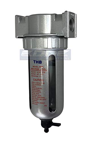 1/2" Particulate filter water trap seperator
|
9.1/10 | Buy |
| Best Premium |
 1/2" NPT Air Compressor Dryer
|
9.1/10 | Buy |
| Best Budget |
 RIH 1/4" NPT Air Dryer for Compressor
|
8.3/10 | Buy |
 LE LEMATEC Inline Air Compressor Water Separator
|
8.3/10 | Buy | |
 DEWALT Inline Dessicant Dryer with Viewing Window
|
8.1/10 | Buy | |
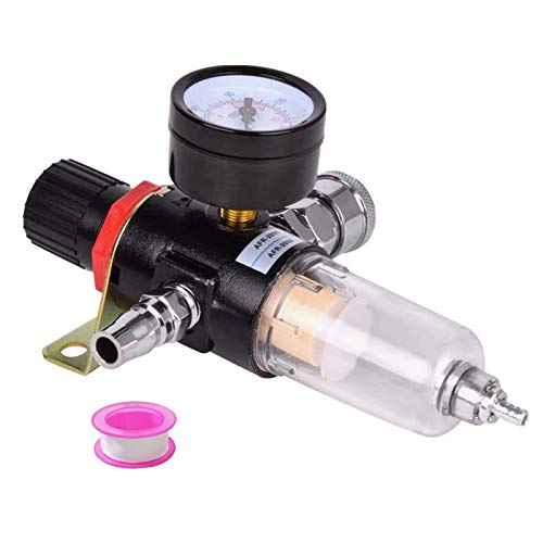 Hotusi 1/4" BSP Air Compressor Moisture Filter
|
7.8/10 | Buy | |
 3/4" NPT Air Compressor Dryer
|
7.8/10 | Buy |
Methods for Eliminating Water in Compressed Air Systems
Compressed air systems naturally generate water every time the pump cycles, making moisture management a primary operational challenge for any workshop. Atmospheric air contains relative humidity that concentrates dramatically when forced into a pressurized receiver tank. Left unchecked, this moisture travels into hoses, rusts pneumatic motor cylinders, causes fisheyes in paint coatings, and ruins plasma torch consumables. Eliminating this water requires understanding the thermodynamic cooling process, establishing strict tank drainage routines, and installing multi-stage filtration hardware along your air lines.
The Thermodynamics of Moisture Accumulation in Compressed Air
Ambient air always contains gaseous water vapor, with warmer environments holding significantly higher moisture levels. When an air compressor draws in ambient air, it compresses that atmospheric volume into a fraction of its original physical space. Compressing the air molecules generates substantial friction and thermal energy, which keeps the concentrated moisture in a vaporized state inside the pump cylinder. This superheated air holds water vapor easily until it exits the pump head and begins moving toward the receiver vessel.
Once the hot compressed air enters the receiver tank, it begins radiating thermal energy outward through the steel tank walls. As the compressed air drops below its pressure dew point, the suspended vapor condenses into liquid water droplets. This liquid collects at the bottom of the tank reservoir, while the remaining air maintains elevated relative humidity as it exits the discharge port. Understanding this temperature drop explains why filtration placed directly at the compressor discharge port often fails to catch vapor before it cools further downstream.
Establishing an Effective Receiver Tank Drainage Routine
The air receiver tank acts as your primary water trap, capturing the heaviest bulk condensation before it reaches your supply lines. Allowing pooled water to linger inside the tank decreases your usable air reserve buffer and accelerates internal tank rust. In severe cases, neglected tanks can accumulate gallons of stagnant rusty water that will eventually surge downstream into your pneumatic tools. Draining the air receiver regularly is the single most important preventative maintenance task for any compressor owner.
Manual thumb petcock valves on older or budget tanks are notorious for sticking and discouraging regular maintenance. Upgrading to a smooth quarter-turn brass ball valve makes draining the tank at the end of every working session quick and effortless. Alternatively, installing an automatic drain valve configured to open whenever line pressure drops ensures accumulated condensation discharges reliably without manual intervention. Auto-drain valves save significant maintenance time and protect equipment from accidental neglect during busy shop hours.
Installing Stage-One Particulate Water Traps
Primary particulate filters represent the first mechanical defense positioned downstream from your air compressor discharge manifold. These units use internal centrifugal baffles to spin incoming airflow and fling heavy water droplets against the bowl walls. The captured liquid drops into the sump below the baffle plate, where it cannot be re-entrained into the outgoing airstream. Most particulate filter bowls feature clear sight glasses or transparent polycarbonate guards that let you monitor water levels safely during operation.
A 5-micron porous bronze or synthetic filter element captures large water droplets alongside rust flakes and pipe scale. Units like the THB half-inch particulate filter or the RIH quarter-inch separator handle steady flow rates while removing the bulk of raw liquid moisture. These filters function best when placed several feet away from the compressor tank, allowing hot air to cool down sufficiently before entering the filter bowl. Positioning the filter after an extended pipe run ensures that gaseous vapor has already condensed into liquid droplets that the 5-micron element can trap.
Utilizing Coalescing Filters for Aerosol Separation
Standard particulate filters catch large bulk droplets, but microscopic moisture mists and oil aerosols easily pass right through them. Coalescing filters feature an ultra-dense borosilicate microglass matrix, often rated down to 0.01 microns, designed to capture sub-micron droplets. As tiny mist particles pass through the fibrous matrix, they collide, combine into larger droplets, and drain downward into the collection bowl. This coalescing action removes up to 99.98 percent of suspended liquid aerosols that would otherwise contaminate sensitive pneumatic tasks.
Integrating a coalescing stage is critical if you operate an oil-lubricated compressor, as pump blow-by creates oil-water emulsions that ruin paint finishes. Multi-stage systems position a 0.01-micron coalescing element directly after the 5-micron particulate filter. This staged arrangement prevents larger debris from prematurely clogging the delicate coalescing media, extending filter service life and maintaining clean airflow. Coalescing units equipped with pop-up differential pressure indicators alert operators exactly when the internal element requires replacement.
Deep Drying with Desiccant Systems for Critical Applications
Mechanical filtration separates liquid droplets, but it cannot extract water that remains in a gaseous vapor state. Desiccant air dryers resolve this limitation by directing compressed air through a packed bed of silica gel or activated alumina beads. The porous chemical structure of the desiccant adsorbs water molecules directly from the airflow, driving the pressure dew point down to deep sub-zero levels. This stage is indispensable for automotive spray painting, powder coating, sandblasting, and precision plasma cutting operations.
Multi-stage assemblies, like the RVMARINEPAT four-stage system, integrate dedicated desiccant bowls after particulate and coalescing filtration. Most modern desiccant beads feature color-shifting indicators that turn from bright blue to pink as they absorb moisture and reach saturation. Once the beads turn pink, they must be replaced with fresh beads or baked in an oven to drive off trapped moisture. Keeping spare packs of desiccant beads on hand ensures your critical air operations never grind to a halt when beads become saturated.
Deploying Point-of-Use Filters at the Tool Inlet
Even with a central filtration setup, warm compressed air traveling through long rubber hose lines can continue to cool and condense additional moisture. Placing a compact, lightweight filter directly at the inlet of sensitive tools provides essential secondary insurance. Point-of-use separators are especially critical for HVLP spray guns, sandblasting nozzles, and plasma cutting torches where a single drop of water causes immediate project failure. These miniature filters catch any residual moisture that forms inside flexible drop lines between the wall regulator and your tool.
Compact inline separators, such as the LE LEMATEC aluminum model, weigh only a few ounces and mount directly between the air hose and spray gun handle. These point-of-use filters feature internal sintered bronze elements rated for up to 200 PSI, stopping residual condensation right before it enters the air nozzle. Push-button drain valves on clear polycarbonate bowls allow operators to eject trapped moisture instantly during mid-project inspections without depressurizing the line. Using a lightweight inline unit protects expensive air tools while maintaining ergonomic balance and maneuverability for precise finishing work.
Designing Rigid Workshop Piping to Condense and Trap Water
Relying exclusively on filters can quickly overwhelm your desiccant beads if your piping layout fails to handle bulk cooling effectively. Installing a dedicated rigid air line system made from copper or modular aluminum allows hot compressed air to dissipate thermal energy across long runs. As the air travels along the hardline piping, it drops in temperature, forcing suspended vapor to condense on the interior pipe walls before reaching your tool drops. PVC piping must never be used for compressed air distribution because pressurized plastic can shatter into dangerous high-velocity shards.
Piping runs should always slope slightly downward, away from the compressor pump, at a grade of roughly one inch per ten feet of run. At the end of each sloped run and along intermediate low spots, install vertical drop legs equipped with drain valves. Liquid condensation follows gravity along the bottom of the sloped pipe and collects safely in the drop legs, leaving the main airflow path dry and clear. Equipping these drop legs with manual ball valves or automated float drains allows you to purge accumulated liquid from the system effortlessly.
Fabricating Gooseneck Riser Drops for Workstation Feeds
Taking air directly from the bottom or side of a main header pipe is a common layout error that directs pooled liquid straight to your tools. To prevent this, every workstation drop should emerge from the top of the main supply line using a gooseneck or inverted-U riser fitting. The air rises upward out of the header before looping 180 degrees downward toward the tool regulator. This upward routing forces heavy condensation to remain in the main pipe rather than trickling into your tool lines.
Because liquid water hugs the bottom of the main supply pipe under the influence of gravity, it bypasses the top-mounted riser pipe entirely. The water continues flowing toward the dedicated terminal drain leg, while only the cleaner, lighter air enters the drop pipe. Combining top-mounted risers with a ball valve drain at the bottom of each vertical drop creates a passive separation system that requires zero consumables. This proven workshop plumbing technique dramatically reduces the moisture burden placed on your downstream filters and desiccant dryers.
Balancing Port Sizes and Dynamic Airflow Restrictions
Every filter, coalescing element, and desiccant bowl introduced into your pneumatic plumbing creates a slight restriction to airflow. If your filter ports are undersized, high-consumption tools like dual-action sanders or impact wrenches will suffer from severe dynamic pressure drops. Choosing appropriately sized NPT ports ensures that your air drying system maintains sufficient cubic feet per minute without choking tool performance. Checking tool CFM requirements against filter flow ratings prevents premature pressure loss during heavy continuous use.
For primary distribution manifolds and high-volume shop systems, half-inch or three-quarter-inch NPT dryers, like DAIERTEK multi-stage units, provide ample flow capacity. Smaller quarter-inch ports, such as the RIH AF2000-02 or Hotusi moisture filter, are suited for low-CFM tools, dedicated tire inflation drops, or individual benchtop regulators. Matching the port diameter to your continuous pneumatic consumption ensures steady operating pressure under demanding workloads. Locking regulator knobs and clear pressure gauges help maintain stable pressure output across various workshop applications.
Implementing an Inspection and Element Replacement Schedule
Preventing moisture accumulation is an ongoing maintenance discipline that demands consistent inspection to remain effective. Over time, particulate filter elements collect rust scale and pipe debris, while coalescing membranes become fouled with oil vapors. When elements become clogged, they cause noticeable pressure drops across the regulator and can eventually rupture, sending trapped debris downstream. Establishing a routine inspection schedule prevents unexpected downtime and keeps your compressed air supply consistently clean.
Check the sight glasses on your filter bowls weekly to monitor liquid collection and verify that auto-drain floats are seating cleanly. Replace 5-micron particulate elements and 0.01-micron coalescing cartridges whenever differential indicators flag high resistance or at regular six-month intervals. Monitoring your desiccant bead color daily ensures you never run spray painting equipment or plasma cutters with saturated drying media. Keeping replacement filter elements and fresh desiccant on your shop shelf eliminates delays when routine maintenance is due.
Practical Strategy for Reliable Dry Workshop Air
Eliminating compressed air moisture requires combining daily operational habits with strategic filtration hardware and passive plumbing design. Start by opening the bottom receiver drain after every single use to eject bulk condensation before rust forms inside the steel vessel. Position high-flow particulate and coalescing filters several feet downstream where cooler air temperatures encourage liquid separation. Back up your primary setup with a desiccant drying canister and a lightweight point-of-use filter whenever running moisture-sensitive tools.
Designing your workshop air lines with sloped headers, top-takeoff goosenecks, and bottom drop legs prevents water from ever reaching your hoses. Routine element replacements and frequent visual checks ensure that your drying equipment operates at peak efficiency year-round. Implementing these coordinated moisture defense layers protects your pneumatic tool investments and guarantees professional, defect-free results in your shop.
About the author
Bob Beacham is an experienced tools and workshop writer with deep knowledge of power equipment, mechanical systems, and practical DIY applications. His coverage of air compressors, welding equipment, saws, and workshop tools helps translate technical specifications into useful guidance for homeowners and serious DIYers.