
How to Connect Two Air Compressors in Parallel: Practical Setup Guide for 2026
Learn how to connect two air compressors in parallel to double CFM output for demanding pneumatic tools in October 2026.
 By Tom Scalisi
Updated October 8, 2026
By Tom Scalisi
Updated October 8, 2026

Running high-demand pneumatic tools like continuous sprayers, dual framing nailers, or rotary grinders often pushes a single compact compressor beyond its limits. When a single motor cannot produce enough air volume to sustain working pressure, learning how to connect two air compressors in parallel offers a practical way to boost delivery without buying an expensive stationary shop compressor. Pairing two smaller units combines their total air output while keeping operating pressure manageable for common shop tasks.
Combining two pneumatic setups requires attention to electrical supply limits, manifold fittings, and pressure switch coordination. Many home workshops run into difficulties when dual motors try to pull startup amperage from the same circuit, leading to nuisance breaker trips. By balancing your electrical distribution, plumbing the tanks into a shared header line with proper check valves, and dialing in pressure settings, you can create a reliable dual-pump system that maintains steady pressure for demanding pneumatic jobs.
| Award | Product | ACR Score About ACR ScoreThe ACR Score is our own rating from 0 to 10, based on performance, design and build, ease of use, and value. It reflects independent research and is never influenced by manufacturers, retailers, or affiliate commissions. Learn more › | |
|---|---|---|---|
| Best Overall |
Stealth Air Compressor 2 Gallon
|
9.2/10 | Buy |
| Best Budget |
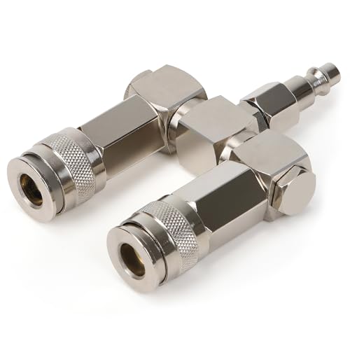 2-Way Air Hose Splitter, 1/4" NPT Air Compressor
|
7.8/10 | Buy |
 VEVOR Air Compressor, 2 Gallon Steel Tank
|
7.8/10 | Buy |
Configuring Dual Air Compressors in Parallel for Maximum Airflow
Connecting two air compressors in a parallel arrangement combines their volume output while maintaining standard line pressure. In a parallel pneumatic circuit, both compressor tanks discharge into a shared manifold line that feeds your tools. This design differs from a series connection, which feeds the output of one compressor into the intake of another to raise pressure. Parallel setups focus strictly on increasing delivered cubic feet per minute (CFM) and overall storage buffer to keep air tools from stalling.
Understanding CFM and PSI Dynamics in Parallel Systems
Air tools require a specific volume of air delivered at a stable operating pressure to function properly. When you plumb two compressors in parallel, their individual CFM ratings add together at any given operating pressure. If you pair two portable machines rated at approximately 2 CFM at 90 PSI each, the combined manifold delivers roughly 4 CFM at that same pressure level. This extra flow prevents severe pressure drops during continuous tool operation.
Operating pressure behaves differently than air volume in a combined pneumatic system. The maximum working pressure of your shared system never exceeds the output setting of the individual units. If one compressor stops pumping at 125 PSI and the second stops at 120 PSI, your combined tank pressure peaks at the lower cut-off threshold unless properly isolated. Pressure does not multiply; only the available flow rate and reserve storage volume increase.
Air buffer capacity also expands when linking two tanks together. Combining two 2-gallon tanks creates a 4-gallon storage reservoir that cushions the system against brief spikes in air consumption. This increased buffer smooths out pressure fluctuations when running intermittent tools like framing nailers or pneumatic staplers. However, continuous air tools still rely entirely on the combined pump displacement once the storage reserve drops below working pressure.
Managing Electrical Supply and Dedicated Branch Circuits
Electrical circuit limitations represent the most common pitfall when assembling a dual-compressor configuration. Electric compressor motors draw substantial running current, but their initial startup inrush current is significantly higher. Attempting to power two compressors from the same 15-amp or 20-amp 120-volt household branch circuit will almost certainly trip the circuit breaker as soon as the second motor cycles on. High inductive motor loads demand careful distribution across your workshop electrical panel.
Each air compressor should always be plugged into its own dedicated electrical circuit. For standard residential garages, this means locating two separate 120-volt wall receptacles wired back to different individual circuit breakers in the main service panel. Running one machine on a 15-amp general lighting circuit while the other sits on a dedicated 20-amp utility branch provides the clean power each motor requires. Always avoid light-duty extension cords, as extended wiring causes severe voltage drops that overheat motor windings and trigger thermal overload switches.
Staggering motor startup cycles also helps protect electrical circuits from simultaneous power surges. When both compressors cut in at the exact same fraction of a second, the shared electrical service experiences a massive cumulative spike. Setting slightly different pressure switch cut-in points ensures one motor starts first, stabilizing line voltage before the second motor begins pumping. This operational offset keeps both machines running smoothly without shocking your electrical panel.
Essential Plumbing Hardware and Manifold Components
Assembling a parallel connection requires sturdy pneumatic fittings that can withstand continuous vibration and tank pressure. The core component is a heavy-duty tee fitting or a multi-port manifold that joins two incoming air lines into a single outgoing supply line. Hardware like the 2-Way Air Hose Splitter, 1/4″ NPT Air Compressor connector provides a convenient junction point, featuring nickel-plated steel construction rated for up to 300 PSI working pressure. Its rotating 360-degree swivel design helps prevent hose kinks when routing lines between two stationary or portable tanks.
One-way check valves are critical safety and functional elements in any parallel air piping arrangement. Each compressor line feeding into the shared manifold should feature an inline brass check valve oriented in the direction of downstream airflow. These check valves prevent pressurized air from backfeeding from one tank into the other if one unit shuts down or vents through its unloader valve. Without check valves, air will take the path of least resistance and bleed backward through the weaker or idle machine.
Hose diameter selection directly influences how much air actually reaches your pneumatic tools. While standard 1/4-inch quick-connect fittings are common on portable compressors, using 3/8-inch inner diameter hoses between each compressor tank and the central junction minimizes friction loss. Restrictive fittings and undersized supply hoses create dynamic pressure drops, neutralizing the CFM benefits gained by linking two machines together. Quality brass or steel industrial quick-connect couplers ensure tight, leak-free seals across every connection point.
Step-by-Step Parallel Connection Procedure
Safety preparation is the first step before altering any pneumatic lines or connecting fittings. Disconnect both air compressors from their electrical outlets to prevent unexpected motor activation. Open the tank drain valves on both units completely and let all stored air discharge until tank pressure gauges read zero PSI. Never loosen, tighten, or thread pneumatic fittings into a tank or manifold while pressure remains trapped inside the system.
Begin the physical assembly by installing high-flow male quick-connect plugs onto short leader hoses coming from each compressor outlet. If your compressors have built-in pressure regulators, open both factory regulator knobs completely so that tank pressure flows unimpeded into the connecting lines. Thread an inline brass check valve into each compressor discharge port if your machines lack internal one-way outlet protection, ensuring arrow markings point toward the central manifold.
Connect both leader lines into the dual inlet ports of your central tee fitting or swivel manifold. Position the manifold securely between the two compressors, leaving enough slack in the hoses so machine vibrations do not strain the threaded joints. Apply PTFE thread sealant tape or paste to all fixed NPT pipe threads to stop micro-leaks before they start. Attach your primary workshop distribution hose to the single outlet side of the manifold, routing it to a centralized downstream pressure regulator.
Perform a thorough leak inspection before putting the system into active service. Close both tank drain valves, plug the power cords into separate dedicated electrical circuits, and power on one compressor at a time until both tanks reach full cut-off pressure. Spray a mild soapy water solution onto every threaded fitting, quick-connect coupler, and manifold joint. If expanding bubbles appear, depressurize the tanks immediately and tighten or reseal the affected fitting.
Calibrating Pressure Switches and Regulators for Lead-Lag Operation
Managing the cycling behavior of two linked air compressors requires a deliberate pressure switch strategy. In an ideal setup, two identical pressure switches would engage at the exact same PSI, but mechanical manufacturing tolerances make simultaneous cycling nearly impossible. Setting up a lead-lag configuration is generally the most efficient approach for dual-pump systems. In this arrangement, one compressor acts as the primary supplier for light work, while the secondary unit engages only when heavy tool usage causes line pressure to dip lower.
To establish a lead-lag cycle, adjust or select units with slightly offset factory cut-in thresholds. For example, if your primary unit has a cut-in threshold of 95 PSI and a cut-out threshold of 125 PSI, configure the second compressor to cut in around 85 PSI. When you use small amounts of air for quick jobs, only the lead compressor starts, saving electricity and mechanical wear. When high-demand tools drain air faster than the lead pump can deliver, system pressure drops past 85 PSI, triggering the second compressor to supply supplemental CFM.
Downstream pressure regulation should always take place after the two air streams merge into the common manifold. Trying to regulate each compressor independently before the junction creates an unbalanced flow where one unit constantly fights against the line pressure of the other. Keep both tank outlet regulators fully open, and install a single, high-flow air regulator on the discharge port of your shared tee. This provides smooth, stable pressure directly to your tools regardless of which pump is actively running.
Evaluating Output with Paired Portable Compressors
Combining compact portable compressors illustrates how effective parallel setups can be in a small workshop. For instance, pairing the Stealth Air Compressor 2 Gallon with the VEVOR Air Compressor, 2 Gallon Steel Tank creates an agile, high-output setup. The Stealth unit features a 3/4 horsepower oil-free motor delivering 1.8 CFM at 90 PSI with a peak pressure of 125 PSI, running at a quiet 60-decibel operating level. Its low-vibration Q235B steel construction makes it simple to position right alongside secondary shop equipment.
The companion VEVOR unit brings a 1 horsepower oil-free motor producing 2.1 CFM at 90 PSI with a 120 PSI maximum pressure rating. When joined via a central 1/4-inch NPT splitter, their combined delivery reaches approximately 3.9 CFM at 90 PSI. That combined volume allows you to operate medium-demand tools like intermittent paint spray guns, pneumatic die grinders, or dual finish nailers that neither compact compressor could support on its own. Total tank storage expands to 4 gallons, providing better pressure stability across short bursts of work.
Operational noise remains manageable when combining quiet-running modern units. The Stealth unit runs below 60 decibels while the VEVOR compressor is built with intake mufflers rated around 81 decibels. Because both machines utilize oil-free dual-piston mechanisms, they require minimal maintenance and do not discharge oil mist into your shared delivery lines. This clean, oil-free airflow protects finish work, spray painting setups, and delicate pneumatic tool internals from oil contamination.
Moisture Draining and Routine Dual-Tank Maintenance
Condensation management becomes doubly important when operating two connected compressor tanks. Compressing ambient air generates heat, and as that air cools inside the tanks, moisture falls out of suspension and pools at the bottom. Because both tanks collect water independently, you must open the drain valves on both units at the end of every work session. Leaving water inside either tank promotes internal steel corrosion and leads to rusty water spraying through your pneumatic tools.
Inspect the tank drain petcocks regularly to ensure they have not become clogged with sediment or scale. Steel tanks like the Q235B structural shells on the Stealth and VEVOR units feature robust construction, but long-term durability depends directly on keeping moisture cleared out. If a factory needle valve becomes stiff or leaks air, replacing it with a quarter-turn brass ball valve makes daily draining faster and more reliable. Always discharge water with low tank pressure remaining to force trapped liquid out through the valve opening.
Thermal management is another key ownership factor for parallel systems running long duty cycles. Oil-free motors rely on cooling fans and intake air movement to dissipate friction heat from pistons and cylinders. Both the Stealth and VEVOR models feature built-in overheating protection to prevent motor damage if ambient temperatures climb. Keep both units situated in well-ventilated areas with clean intake filters so airflow stays unrestricted during extended pump recovery runs.
Safety Precautions and Pressure Relief Protection
Operating a dual-compressor manifold system requires strict adherence to baseline pneumatic safety guidelines. Every connected compressor tank must retain its factory ASME-certified safety relief valve in working order. Never plug, remove, or modify a tank safety valve to eliminate pressure venting. These spring-loaded valves serve as essential emergency fail-safes designed to pop open automatically if a pressure switch sticks and over-pressurizes a tank beyond safe structural ratings.
Test the safety relief valves periodically by pulling their manual release rings while the tanks hold light pressure. Air should hiss out sharply and reseat cleanly as soon as you release the ring. In addition, check that unloader valves on both machines vent head pressure with an audible hiss when the motors shut off. If an unloader valve fails to release trapped air, the motor will struggle to turn against high head pressure during its next cycle, potentially tripping the circuit breaker.
Always inspect connected air lines, swivels, and fittings for signs of fatigue, cracking, or surface wear. High-pressure air lines under continuous vibration can loosen threaded joints over time. Setting up your parallel air compressor system with quality components, dedicated electrical circuits, and routine maintenance checks delivers the dependable high-CFM airflow needed to tackle demanding pneumatic projects safely.
About the author
Tom Scalisi brings more than two decades of experience in construction, building maintenance, contracting, and hands-on tool use. His practical understanding of power tools, automotive work, repairs, and jobsite equipment helps readers evaluate compressors based on real workloads rather than specifications alone.