
How to Calculate Cfm of Air Compressor: Practical Guide for 2026
Learn how to calculate cfm of air compressor using tank fill formulas and pressure tests in October 2026. Sizing your compressor ensures air tools run reliably without pressure drop.
 By Tom Scalisi
Updated October 8, 2026
By Tom Scalisi
Updated October 8, 2026

Continuous air tools such as rotary sanders, paint sprayers, and die grinders often stall unexpectedly when a workshop pump cannot keep up with air demand. Many operators assume that high tank pressure guarantees steady performance, but tank pressure only provides a temporary buffer before the motor must replenish the supply. Understanding how to calculate cfm of air compressor allows woodworkers, auto mechanics, and DIY enthusiasts to determine true continuous delivery under load. By calculating this volume accurately, buyers avoid the frustration of rapid pressure drop, constant motor cycling, and unexpected tool stalls during critical workshop operations.
Air compressors rely on volumetric airflow measured in cubic feet per minute to power pneumatic tools smoothly across varied duty cycles. A pump delivering inadequate airflow forces pneumatic tools to lose torque, while an oversized industrial unit draws unnecessary electrical amperage on standard residential branch circuits. Evaluating delivered air output through practical tank fill formulas reveals true pump capabilities rather than optimistic peak horsepower labels. This straightforward assessment helps operators match pneumatic equipment properly and select reliable machinery for garage workshops or active jobsites.
| Award | Product | ACR Score About ACR ScoreThe ACR Score is our own rating from 0 to 10, based on performance, design and build, ease of use, and value. It reflects independent research and is never influenced by manufacturers, retailers, or affiliate commissions. Learn more › | |
|---|---|---|---|
|
California Air Tools CAT-1P1060S Light & Quiet
|
8.6/10 | Buy | |
 California Air Tools 8010A 1.0 HP Ultra Quiet
|
8.0/10 | Buy | |
| Best Overall |
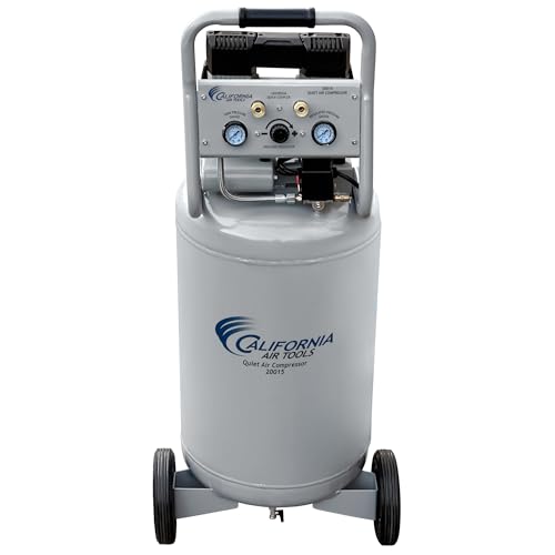 California Air Tools CAT 20015 1.5 HP Ultra Quiet
|
8.9/10 | Buy |
 California Air Tools 8010AAD 1.0 HP Ultra Quiet
|
8.6/10 | Buy | |
 California Air Tools 8010AD 1.0 HP Ultra Quiet
|
8.6/10 | Buy |
Measuring and Calculating True Air Compressor CFM
Determining the precise airflow of an air compressor prevents costly equipment mismatches and frustrating workshop downtime. Air volume is universally measured in cubic feet per minute, representing the amount of free air compressed and delivered to an air tool under specific pressure conditions. While marketing materials frequently highlight motor horsepower or storage tank capacity, actual CFM delivery dictates whether pneumatic tools operate efficiently. Calculating this output manually using physical tank fill tests cuts through marketing claims and reveals how the compression pump performs in a real workshop environment.
The Physics of Atmospheric Air Compression
Air compression relies on the physical relationship between atmospheric volume, operating pressure, and storage tank containment. Under standard ambient conditions at sea level, atmospheric air exerts roughly 14.7 pounds per square inch of absolute pressure. When a compressor pump draws in ambient air, reciprocating pistons reduce its physical volume and force it into a rigid storage vessel. Because air is compressible, crowding more air molecules into a fixed container increases internal pressure proportionally.
Understanding free air delivery requires distinguishing between stored air volume and active pump displacement. Stored volume represents the physical quantity of compressed gas resting inside the reservoir at an elevated pressure level. In contrast, cubic feet per minute represents the volumetric rate at which the pump can continuously intake, compress, and discharge ambient air into that reservoir. A high-pressure tank provides a short buffer of stored energy, but sustained pneumatic tool operation depends entirely on continuous pump displacement.
The Mathematical Formula for Compressor CFM
Calculating compressor CFM through a physical pump test requires a mathematical formula that translates tank dimensions and pressure changes over time into free air volume. The standard formula states that CFM equals the tank volume in cubic feet multiplied by the pressure increase in atmospheres, divided by the elapsed time in minutes. Because compressor tanks are manufactured and labeled in liquid gallons, the internal volume must first be converted into cubic feet. One cubic foot equals approximately 7.48 US liquid gallons, creating a direct geometric conversion factor for any workshop tank.
Pressure measurements must also be converted from gauge pressure into atmospheric units to account for compression ratios. Standard pressure gauges read zero at ambient atmospheric pressure, which means absolute pressure requires adding 14.7 PSI to the gauge reading. Dividing the difference between final gauge pressure and initial gauge pressure by 14.7 yields the total atmospheres of air packed into the vessel. Multiplying this pressure ratio by tank volume in cubic feet and dividing by fill time in minutes produces true volumetric output.
Step-by-Step Tank Fill Test Procedure
Executing an accurate tank fill test requires proper preparation to avoid measurement distortion or mechanical hazards. Disconnect all pneumatic hoses and air tools from the outlet couplers to eliminate downstream line volume. Shut down the electric motor, unplug the unit from wall power, and locate the bottom tank drain valve. Slowly open the drain valve to discharge trapped moisture and exhaust all residual tank pressure until the pressure gauge settles at zero PSI.
Close the drain valve tightly once all air and condensation have completely cleared the reservoir. Inspect the air intake filter assembly on the pump head to confirm the element is free from wood dust, paint residue, or shop debris. A clogged intake restriction starves the pump of atmospheric air, artificially depressing test results and skewing volumetric calculations. Ensure the compressor sits level on solid flooring, and verify that the electrical supply matches manufacturer specifications to avoid motor lag during startup.
Prepare a reliable digital stopwatch and reconnect the compressor directly to a standard wall outlet. Switch the compressor power toggle to the on position while simultaneously starting the stopwatch at the exact moment the motor engages. Observe the main tank pressure gauge as the pump forces air into the empty receiver, and stop the timer immediately when the pressure switch cuts power at cut-out pressure. Record the elapsed time in seconds along with the final pressure reading to complete the test data.
Worked Calculation with an 8-Gallon Compressor
Walking through an example using realistic equipment specifications clarifies how the mathematical components interact. Consider an 8-gallon portable unit such as the California Air Tools 8010AAD, which features an aluminum tank and a dual-piston 1.0 HP pump. Manufacturer specifications list a total tank fill time of 165 seconds to reach a maximum cut-out pressure of 120 PSI from a completely empty state. Using these specific operational parameters illustrates how the formula produces genuine volumetric air ratings.
First, convert the 8-gallon capacity into cubic feet by dividing 8 by 7.48, which yields approximately 1.07 cubic feet of internal physical tank volume. Next, calculate the atmospheric pressure ratio by dividing the 120 PSI pressure rise by 14.7, which equals approximately 8.16 atmospheres of compressed air. Multiplying 1.07 cubic feet by 8.16 atmospheres reveals that the pump packed roughly 8.73 cubic feet of free air into the tank. Dividing 8.73 cubic feet by 2.75 minutes (165 seconds divided by 60) yields an average airflow delivery of approximately 3.17 CFM across the entire cycle.
Measuring Working CFM During Pressure Recovery
Timing a fill cycle from zero to maximum cut-out pressure provides an average volumetric output, but air compressors do not deliver constant airflow at every pressure level. As pressure inside the tank climbs, the pump pistons encounter greater physical resistance, causing delivered airflow to taper off. Most pneumatic tools operate between 70 PSI and 90 PSI, meaning operators need to know airflow delivery specifically within that functional window. Testing recovery cycle speed provides a much more accurate reflection of working performance.
To measure working CFM, allow the compressor to fill completely until the pressure switch automatically shuts off the motor. Bleed off tank pressure using an air nozzle until the switch reaches its cut-in threshold, restarting the pump at roughly 90 PSI. Time the recovery cycle until the motor shuts off at 120 PSI. For example, the California Air Tools 8010AD with an 8-gallon steel tank lists a recovery time of 60 seconds from 90 to 120 PSI. Dividing the resulting 2.18 cubic feet of air by one minute yields 2.18 CFM, confirming the manufacturer rating of 2.20 CFM at 90 PSI.
Distinguishing Between CFM, SCFM, and Operating PSI
Navigating compressor technical documentation requires distinguishing between standard cubic feet per minute and raw cubic feet per minute. Standard cubic feet per minute, abbreviated as SCFM, standardizes airflow measurements to a reference environment of 68 degrees Fahrenheit, 14.7 PSI atmospheric pressure, and 36 percent relative humidity. Raw CFM simply measures volumetric displacement under prevailing ambient conditions, which may fluctuate based on garage temperature and elevation. For most workshop calculations, CFM and SCFM values remain sufficiently close for equipment matching.
The pressure at which airflow is rated represents the most critical specification on any tool or compressor label. Manufacturers commonly provide two separate airflow ratings: CFM at 40 PSI and CFM at 90 PSI. At lower pressures such as 40 PSI, pistons compress air with minimal resistance, yielding higher volume numbers. A pump like the California Air Tools CAT 20015 produces 4.00 CFM at 40 PSI, but its output drops to 2.90 CFM at 90 PSI as internal backpressure increases. Always match tool demand at 90 PSI directly to compressor delivered CFM at that identical pressure.
Sizing Compressor Output to Pneumatic Tool Demand
Calculating air compressor capacity must extend beyond pump output to encompass the air consumption patterns of specific pneumatic tools. Pneumatic equipment generally divides into intermittent use tools and continuous duty tools. Intermittent tools, such as brad nailers, finish nailers, and staple guns, consume small bursts of air only when fired. A compact unit like the California Air Tools CAT-1P1060S delivers 1.20 CFM at 90 PSI from a 0.6 HP motor, which easily supports finish nailing, tire inflation, and airbrushing without stalling.
Continuous tools, including orbital sanders, die grinders, needle scalers, and HVLP paint spray guns, present a far greater challenge for small compressors. These tools draw air unceasingly while the trigger remains depressed, quickly draining small reservoirs and demanding massive pump displacement. Applying a standard engineering safety factor ensures the compressor keeps pace with daily workshop demands. Sizing rules recommend multiplying the highest individual tool CFM requirement by 1.25 or 1.5 to establish the minimum necessary compressor output, preventing the pump from running constantly at its thermal limit.
Tank Buffer Reserves and Pump Duty Cycles
Storage tank capacity does not generate additional air, but it acts as an essential energy reservoir between pumping cycles. A large receiver tank buffers brief periods when tool consumption exceeds the continuous delivery rate of the pump. For instance, the California Air Tools CAT 20015 pairs a 1.5 HP motor with a 20-gallon steel tank, providing substantial stored volume. This larger buffer allows an operator to run higher-draw tools intermittently without experiencing sudden pressure collapses at the regulator.
Duty cycle represents the percentage of time a compressor pump can safely run within a given operating window without overheating. Most consumer and light commercial compressors carry duty cycle ratings between 50 percent and 70 percent. Low-RPM motor design significantly enhances pump durability and heat management under demanding workshop conditions. Dual-piston oil-free pumps operating at 1,680 RPM to 1,750 RPM cut operational heat and mechanical wear, allowing systems to achieve lifespans exceeding 3,000 hours before wear while maintaining clean, oil-free airflow.
Correcting Common Airflow and Measurement Losses
When a compressor fails to achieve its calculated CFM or struggles to maintain pressure, internal and external losses are usually responsible. Air leaks along distribution plumbing, threaded fittings, and quick-connect couplers create constant parasitic volume loss. A pinhole leak in an air hose or a worn rubber O-ring in a female coupler can bleed away several cubic feet of air per hour. Inspecting fittings with a soapy water solution quickly identifies bubbling leaks that sap delivery volume.
Restricted air filtration and moisture buildup also degrade delivered volume over time. An intake filter loaded with airborne particles chokes atmospheric induction, increasing fill times and decreasing calculated CFM. Similarly, neglecting daily tank draining allows condensed water to accumulate at the bottom of the vessel, stealing physical storage capacity. Models such as the California Air Tools 8010AAD and 8010AD feature automatic drain valves that purge moisture efficiently, protecting internal tank space and preventing rust.
Electrical line loss can also impair motor performance and reduce pump displacement speed. Long, light-duty extension cords cause voltage drops that starve electric motors of necessary running current. When voltage sags, electric motors run hotter, spin slower, and risk tripping 15-amp branch circuit breakers upon startup. Connecting compressors directly to dedicated 110V wall outlets with heavy gauge wiring ensures full motor torque and consistent pump RPM during compression cycles.
Practical Workshop Air Sizing Takeaways
Accurately calculating air compressor CFM empowers tool operators to select equipment tailored to their actual pneumatic requirements. Rather than relying on optimistic peak horsepower labels, testing tank fill and recovery times provides an honest assessment of delivered air volume. Matching calculated CFM at 90 PSI with a proper safety margin prevents frustrating pressure dropouts and protects compressor motors from thermal damage. Investing in quiet, low-RPM machinery with adequate tank reserve ensures reliable pneumatic power for years of workshop productivity.
About the author
Tom Scalisi brings more than two decades of experience in construction, building maintenance, contracting, and hands-on tool use. His practical understanding of power tools, automotive work, repairs, and jobsite equipment helps readers evaluate compressors based on real workloads rather than specifications alone.