
How to Connect Two Air Compressors Together: Step-by-Step Guide for 2026
Learn how to connect two air compressors together safely to double CFM output for demanding pneumatic air tools in October 2026.
 By Clint DeBoer
Updated October 8, 2026
By Clint DeBoer
Updated October 8, 2026

Continuous pneumatic tools such as rotary sanders, paint spray guns, and abrasive blasters often consume far more air volume than a single portable compressor can deliver at 90 PSI. When a single pump runs constantly without maintaining regulated line pressure, pairing two units provides a practical way to boost output without purchasing an expensive commercial stationary system. Learning how to connect two air compressors together allows workshop owners and contractors to combine their available CFM output and expand total storage reserve. This configuration ensures that demanding air tools receive steady airflow while keeping individual pumps from overheating.
Achieving a dependable dual-compressor configuration requires more than simply coupling two hoses into an unverified junction. Proper installation demands dedicated electrical branch circuits to prevent startup breaker trips, inline one-way check valves to stop reverse pressurization, and deliberate pressure switch calibration. Utilizing robust components such as high-flow couplers, rated manifold splitters, and proper pipe thread sealing ensures consistent performance across demanding workloads. Understanding the mechanical requirements and electrical safeguards makes linking two air compressors a reliable solution for any busy garage or jobsite.
| Award | Product | ACR Score About ACR ScoreThe ACR Score is our own rating from 0 to 10, based on performance, design and build, ease of use, and value. It reflects independent research and is never influenced by manufacturers, retailers, or affiliate commissions. Learn more › | |
|---|---|---|---|
| Best Overall |
LUMITECO All-Metal Lock-On Air Chuck Tire Inflator
|
9.2/10 | Buy |
| Best Value |
 DEWALT 3-Piece Industrial Coupler and Plug Kit
|
9.2/10 | Buy |
| Best Premium |
 FORNAX 2-Way 1/4-Inch NPT Air Manifold
|
9.2/10 | Buy |
| Best Budget |
 LUMITECO 11-Inch Swivel Tire Inflator Hose
|
9.1/10 | Buy |
 WYNNsky 20-Piece 1/4-Inch Air Tool Kit
|
9.1/10 | Buy | |
 Hromee Compressed Air Outlet Kit
|
8.9/10 | Buy | |
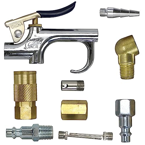 Harrier Hardware 11-Piece Air Compressor Starter
|
8.3/10 | Buy | |
 YOTOO 15-Piece Universal Air Coupler Kit
|
8.3/10 | Buy | |
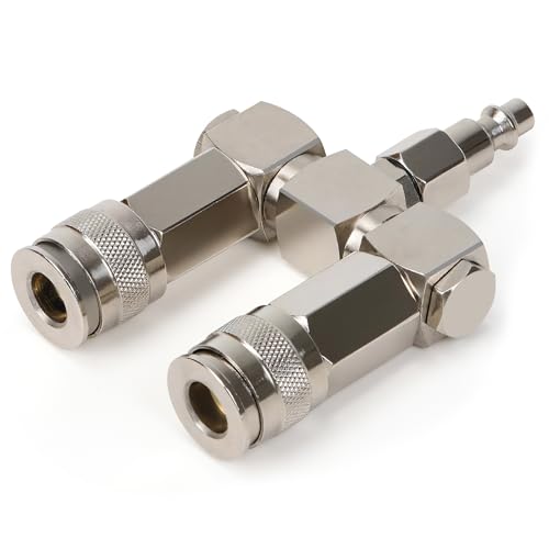 XAQMHSW 2-Way 1/4-Inch NPT Air Hose Splitter
|
7.8/10 | Buy |
LUMITECO All-Metal Lock-On Air Chuck Tire Inflator
The LUMITECO lock-on air chuck adapter converts standard screw-on inflator hoses into a secure, hands-free locking connection rated up to 250 PSI. Built from durable metal alloy with a 90-degree open-flow design, it is an ideal garage upgrade for DIYers and mechanics tired of leaking valve stems.
Pros
- Solid all-metal alloy construction resists workshop wear, drops, and corrosion
- Maximum pressure rating of 250 PSI supports heavy-duty inflation tasks
- Hands-free thumb clamp stops air loss while securing firmly to Schrader valves
- Easily converts tedious twist-on inflator hose ends to instant quick-action clamping
Cons
- Open-flow architecture requires a trigger-actuated inflator gauge or pump switch to prevent continuous air release
- Threads directly to Schrader-pitch hose ends rather than standard 1/4-inch NPT quick couplers
- Locking lever profile can feel tight on deeply recessed wheel valve stems
DEWALT 3-Piece Industrial Coupler and Plug Kit
The DEWALT DXCM036-0207 is a rugged 3-piece steel coupler and plug kit rated for 40 SCFM at 90 PSI and up to 300 Max PSI. Built with corrosion-resistant nickel plating and standard 1/4-inch NPT threads, it allows fast tool swaps without bleeding line pressure, making it ideal for garage hobbyists, trim carpenters, and DIY workshop owners.
Pros
- Heavy-duty nickel-plated steel body resists impact, abrasion, and moisture corrosion
- High airflow rating of 40 SCFM at 90 PSI helps minimize pressure drops during tool operation
- Rated up to 300 Max PSI for broad compatibility with high-pressure portable and stationary compressor setups
- Connects and disconnects smoothly without requiring the air system to be discharged
- Standard 1/4-inch NPT sizing fits the vast majority of consumer and light commercial air tools
Cons
- Steel construction is slightly heavier than aluminum or lightweight composite fittings
- Standard 1/4-inch NPT airflow capacity may cause line restriction for ultra-high-CFM continuous tools like large sandblasters
- Includes only two plugs, so users with extensive pneumatic tool collections will need additional fittings
FORNAX 2-Way 1/4-Inch NPT Air Manifold
This compact in-line splitter enables workshops to run two pneumatic tools simultaneously from a single air supply. Built with an aluminum body and steel quick-connect couplers, it offers a simple plug-and-play setup for routine shop tasks.
Pros
- Operates two air tools from one line
- Sturdy steel fittings on lightweight aluminum housing
- Compact footprint under 4 inches long
- Interchangeable with standard 1/4-inch NPT accessories
Cons
- Limited to two output connections
- Rigid straight design can be awkward in tight quarters
LUMITECO 11-Inch Swivel Tire Inflator Hose
This braided extension hose upgrades portable inflators with a 360-degree swivel lock-on chuck and a protective heat sleeve. It provides a secure, leak-free connection for bicycles, cars, and motorcycles with awkward valve angles.
Pros
- Swivel chuck rotates 360 degrees for awkward valve angles
- Rubber sleeve protects hands from hot compressor fittings
- Converts twist-on connections into quick thumb-press lock-on chucks
- Comes with Presta adapter and extra conversion nuts
Cons
- Short 11-inch length provides limited extra reach
- Open-flow chuck requires active pump connection to prevent deflation
WYNNsky 20-Piece 1/4-Inch Air Tool Kit
This starter package bundles a 15-foot recoil hose, blow gun, and essential fittings into a compact carrying case. It provides the core accessories needed for basic tire inflation, surface dusting, and standard pneumatic tool hookups.
Pros
- Broad 20-piece assortment of standard pneumatic fittings
- Blow gun includes five swappable nozzle attachments
- Self-coiling hose design stores away neatly
- Dedicated case keeps all small adapters organized
Cons
- 120 PSI working limit excludes high-pressure pneumatic tools
- 15-foot hose length limits overall work radius
Hromee Compressed Air Outlet Kit
The Hromee Compressed Air Outlet Kit provides a modular aluminum distribution drop with push-to-connect fittings and a universal coupler for 1/2-inch tubing networks up to 150 PSI. It is an ideal addition for DIY homeowners and workshop mechanics looking to run clean, dedicated pneumatic lines across their garage walls without dragging long hoses.
Pros
- Solid aluminum block construction with versatile top, back, and side mounting configurations
- Push-to-connect 1/2-inch tube fittings simplify layout modifications without threading rigid pipe
- Includes a dedicated shut-off valve and universal quick-connect coupler out of the box
- Rated for standard pneumatic shop setups up to 150 PSI
Cons
- Requires user-supplied 1/2-inch compressed air tubing and mounting hardware
- Limited to systems operating at or below 150 PSI, excluding high-pressure two-stage 175 PSI drops
- Threaded joints require careful thread sealing tape application to prevent slow micro-leaks
Harrier Hardware 11-Piece Air Compressor Starter
The Harrier Hardware 11-piece air compressor accessory kit provides essential pneumatic connections including a blow gun, tire chuck, and standard 1/4-inch NPT fittings. It is a practical starter set for garage DIYers and homeowners looking to handle basic inflation and shop cleanup tasks.
Pros
- Comprehensive 11-piece starter bundle covers basic inflation and workbench cleanup needs.
- Standard 1/4-inch NPT fitting compatibility connects easily with common workshop air hoses.
- Dedicated plastic storage container prevents losing small needles, inflator tips, and fittings.
- Cost-effective entry option for homeowners setting up a newly purchased air compressor.
Cons
- Supplies only one coupler and plug set, requiring extra fittings for multi-tool setups.
- Thread sealant or PTFE tape is not pre-applied and must be added to ensure leak-free connections.
- Designed for light DIY and garage duties rather than high-demand industrial production.
YOTOO 15-Piece Universal Air Coupler Kit
Crafted from lightweight aircraft aluminum, this 15-piece fitting set simplifies pneumatic tool setups with convenient one-handed push connections. Its universal coupler accepts automotive, industrial, and T-type plugs, making it a flexible choice for mixed-tool air compressor lines.
Pros
- Universal coupler fits three common plug styles
- Lightweight aluminum construction resists corrosion
- Six-ball design ensures a solid connection
- Effortless one-handed push-to-connect mechanism
Cons
- Aluminum is softer and wears faster than brass
- Restricted to standard 1/4-inch lines and fittings
XAQMHSW 2-Way 1/4-Inch NPT Air Hose Splitter
Built for dual-tool setups, this nickel-plated steel manifold splits a single compressor line with full 360-degree swivel mobility to minimize hose tangles. It suits garage and workshop users operating standard pneumatic tools up to 300 PSI.
Pros
- Durable nickel-plated steel construction
- 360-degree swivel design prevents hose binding
- Universal coupler accepts multiple plug profiles
- Quick push-to-connect operation requires no tools
Cons
- Confined to standard 1/4-inch NPT connections
- Maximum working pressure capped at 300 PSI
- Simultaneous dual-tool use can reduce airflow volume
Connecting Two Air Compressors for High-Demand Pneumatics
Pairing two air compressors into a single unified air delivery network is one of the most effective ways to overcome airflow limitations in a home garage or busy workshop. Instead of replacing functional portable units with a bulky stationary machine, linking existing tanks allows operators to support continuous air tools like sanders and sprayers. Successfully completing this configuration requires a clear understanding of pneumatic plumbing, pressure switch dynamics, and electrical power demands.
Parallel vs. Series Configurations for Dual Compressors
When planning to link two pneumatic units, operators must understand the fundamental difference between parallel and series connections. In an air compressor setup, a parallel connection means plumbing both compressor tank discharge ports into a single shared delivery line or manifold. Each pump draws ambient air independently, compresses it inside its own storage vessel, and feeds air into the common line as required. This arrangement combines the total air volume, measured in cubic feet per minute, delivered downstream to pneumatic tools.
Connecting two compressors in series involves piping the pressurized discharge output of the first unit directly into the intake air filter of the second compressor. This configuration is exceptionally dangerous and should never be attempted with standard shop compressors. Standard single-stage and two-stage workshop pumps are engineered to ingest ambient atmospheric air at standard temperature and pressure. Forcing pre-compressed, heated air into an uncooled pump cylinder causes severe motor overload, thermal breakdown of lubrication, blown head gaskets, and potential tank failure.
Parallel plumbing represents the only safe and mechanically sound method for hobbyists, woodworkers, and automotive technicians. By allowing each unit to operate at standard atmospheric inlet conditions, both machines maintain their engineered compression ratios and thermal parameters. The combined system preserves the structural integrity of each factory pressure vessel while delivering the aggregate air volume directly to the tool.
How Combined Airflow and Storage Buffers Function
Combining two air compressors affects two distinct performance metrics: airflow volume and storage buffer capacity. Airflow volume, typically rated as standard cubic feet per minute at 90 PSI, dictates whether high-draw continuous air tools can operate without stalling. When two units are connected in parallel, their individual CFM ratings add together directly. For instance, pairing a portable unit delivering 4.0 CFM at 90 PSI with a secondary machine delivering 5.0 CFM yields a combined output of 9.0 CFM at the common regulator.
Storage tank capacity also increases additively across a parallel configuration. Connecting a 6-gallon portable pancake compressor with an auxiliary 20-gallon horizontal compressor provides an aggregate storage buffer of 26 gallons. This expanded buffer creates a substantial pressure cushion that absorbs initial tool demand spikes, such as rapid cycling from multiple framing nailers. The enlarged air reservoir smooths out pressure drops across the line, maintaining steady dynamic working pressure during heavy use.
Maximum working pressure, measured in pounds per square inch, does not add together in a parallel air system. The maximum available line pressure is strictly limited by the lower-rated compressor in the setup. If one unit operates at a maximum of 135 PSI and the second reaches 175 PSI, the overall system must be regulated and managed according to the lower 135 PSI limit to prevent backflow or safety relief issues. Operators must always honor the lowest maximum operating pressure rating among the connected tanks.
Electrical Circuit Sizing and Breaker Protection
Electrical circuit management is the single most common failure point when setting up dual compressors in residential garages. Electric compressor motors draw substantial inrush current during the initial seconds of startup to overcome stationary pump inertia and residual head pressure. A standard 120-volt portable compressor running at full load may draw 12 to 15 continuous amps, with inrush spikes exceeding 25 to 30 amps. Attempting to start two electric compressors on the same 15-amp or 20-amp household branch circuit will immediately trip the thermal circuit breaker.
Each electric air compressor must be plugged into its own dedicated electrical branch circuit backed by an appropriately rated breaker. In a standard home workshop, this means powering unit A from a garage wall receptacle on circuit one and running unit B from a completely separate circuit breaker. Avoid using lightweight extension cords to bridge distances between outlets, as undersized wiring causes severe voltage drop. Voltage drops increase motor running amperage, generating excessive internal winding heat and causing thermal overload protectors to open.
If dedicated outlets are spaced far apart, run longer pneumatic air delivery hoses rather than long electrical extension cords. Air hoses experience manageable pressure drop that can be corrected at the regulator, whereas electrical voltage drop risks permanent motor burnout. Workshop owners utilizing dedicated 240-volt circuits should verify service panel capacity before operating two high-draw stationary pumps simultaneously.
Preventing Reverse Flow with One-Way Check Valves
One-way check valves are indispensable mechanical components in any parallel dual-compressor installation. A check valve permits pressurized air to flow in only one direction, sealing immediately if air attempts to travel backward toward the source. In a dual-compressor configuration, each machine must have a dedicated check valve positioned on its discharge line before the line joins the central manifold. This directional control protects both units against uncontrolled backpressure from the companion compressor.
Without dedicated inline check valves, disparities in tank pressure or regulator cut-off points cause immediate operational problems. If compressor A shuts down while compressor B continues pumping toward a higher cut-out threshold, air from unit B will backfeed directly into unit A. This reverse flow can bleed out through the unloader valve of compressor A, causing continuous air hissing and preventing the system from ever reaching final shutoff pressure. Furthermore, backpressure trapped against an unloader mechanism can prevent a dormant pump from restarting cleanly under zero head pressure.
Quality brass or stainless steel check valves with durable internal springs and synthetic seats provide dependable isolation. Position these valves close to the tank outlets before any flexible hoses reach the common junction block. Verifying that the directional arrow on each valve points downstream toward the shared tool manifold ensures seamless, leak-free operation across frequent motor cycles.
Calibrating Pressure Switches for Staggered Lead-Lag Cycling
Controlling when each compressor starts and stops requires deliberate calibration of the electromechanical pressure switches. Operators can choose between synchronous operation, where both units cycle simultaneously, or a staggered lead-lag configuration. Synchronous operation attempts to match cut-in and cut-out thresholds across both machines, forcing both motors to start together when line pressure drops. While this yields maximum CFM replenishment immediately, it maximizes electrical demand and wear on electrical components.
A staggered lead-lag arrangement is generally the preferred operational strategy for workshops with varied tool demands. In a lead-lag setup, the primary compressor (lead) is set to cut in at a higher pressure, such as 100 PSI, and cut out at 130 PSI. The secondary compressor (lag) has its cut-in threshold dialed slightly lower, perhaps at 85 or 90 PSI, with a matching cut-out at 130 PSI. During light work like brad nailing or tire inflation, only the primary unit starts, saving electrical power and reducing unnecessary shop noise.
When continuous-demand tools like dual-action sanders or abrasive spray guns are triggered, the air consumption quickly exceeds the output of the lead compressor alone. As line pressure drops past 90 PSI, the lag compressor automatically cuts in to assist, doubling available airflow to stabilize working line pressure. Once the tool stops, both compressors continue pumping until reaching their 130 PSI cut-out threshold before shutting down. This staged approach extends overall pump life, minimizes electrical surges, and delivers quiet operation during light-duty tasks.
Essential Manifolds, Couplers, and Delivery Hardware
Building an efficient dual-compressor network requires heavy-duty fittings capable of withstanding continuous operational vibrations and sustained shop pressures. Splitter manifolds such as the FORNAX 2-Way Straight Air Manifold or the steel 2-Way Air Hose Splitter with 1/4-inch NPT connections provide solid junction points for combining two incoming supply lines. When joining two lines into one output, the manifold body serves in reverse, acting as an air collector that joins dual feeds into a unified discharge port.
Quick-connect couplers and plugs must deliver adequate flow capacity without creating severe dynamic restriction. Utilizing industrial quick-connect sets such as the DEWALT 3-Piece Industrial Coupler and Plug Kit, rated for 40 SCFM at 90 PSI and up to 300 PSI, ensures robust sealing and high volume. Lightweight aluminum options, such as the YOTOO 15-piece universal coupler set, offer convenient push-to-connect operation with six-ball retention to eliminate nuisance leaks under fluctuating vibration. Proper pneumatic thread sealing tape, such as the sealant provided in WYNNsky air accessory kits, must be applied to all male NPT threads during assembly to ensure airtight joints.
For permanent shop installations, mounting a rigid distribution block like the Hromee Compressed Air Outlet Kit simplifies wall or bench plumbing. With multiple 3/8-inch female NPT ports and a regulated 1/4-inch outlet, an aluminum distribution block anchors incoming hoses securely and provides a tidy workstation drop. Standard hardware components from kits like the Harrier Hardware starter set supply essential fittings and blow guns for checking connection seals before putting the system into full service.
Step-by-Step Setup and Pressure Verification
Before assembling any fittings or connecting hoses, thoroughly inspect both air compressors and depressurize their storage tanks completely. Disconnect both machines from electrical power to prevent accidental motor cycling during assembly. Open the underside tank drain valves and pull the manual rings on the ASME safety relief valves to confirm that zero residual pressure remains inside either vessel. Clean the external discharge threads with a wire brush to remove debris or aged pipe sealant.
Apply three to four wraps of pneumatic PTFE thread sealing tape in a clockwise direction across all male NPT pipe threads. Thread an appropriately sized one-way check valve directly onto the regulated discharge port or tank tap of each compressor, ensuring the directional arrows point outward toward the tool line. Secure the fittings with matching open-ended wrenches, taking care not to overtighten and crack aluminum or brass valve castings.
Connect high-pressure air hoses from the outlet of each check valve to the dual inlet ports of your central manifold splitter. If using a 2-way manifold with universal couplers, connect matching industrial plugs from each compressor discharge hose directly into the manifold sockets. Attach your primary workshop delivery hose or air tool drop to the common outlet port of the manifold splitter. If using an external master line regulator and filter assembly, install it immediately downstream of the manifold splitter so it regulates combined air volume uniformly.
Close all drain valves, plug each compressor into its dedicated, separate electrical branch circuit, and power on unit A to test initial pressurization. Listen carefully for fitting leaks around the check valves and manifold ports using a soapy water spray solution. Once unit A reaches its cut-out pressure and cycles off cleanly, power on unit B and verify that air does not backfeed into unit A. With both tanks fully pressurized, monitor gauge stability to confirm that the combined system holds static pressure without bleeding down.
Condensation Management and Moisture Filtration
Operating two air compressor pumps simultaneously doubles the volume of atmospheric air compressed, which in turn doubles moisture condensation inside the storage tanks. Warm ambient air contains water vapor that condenses rapidly as compressed air cools against the steel inner walls of the pressure vessels. If left unmanaged, moisture travels downstream into pneumatic tools, washing away internal lubricating oils and causing rust in motor vanes, cylinders, and nailer driver seals.
Daily moisture drainage becomes twice as critical in a dual-compressor setup. Operators should open the underside tank drain valves on both units at the conclusion of every workday to discharge accumulated condensation. If factory thumb petcocks are stiff or inaccessible, retrofitting quarter-turn brass ball drain valves greatly simplifies routine draining. Regularly purging moisture prevents internal tank corrosion and preserves the structural metal thickness of both pressure vessels over years of service.
In addition to daily tank draining, installing a dedicated particulate filter and coalescing moisture separator downstream of the central manifold is strongly advised. High-demand applications like automotive painting or plasma cutting cannot tolerate even fine water droplets. An inline water trap positioned several feet downstream from the manifold allows hot compressed air time to cool, condensing suspended moisture so the filter element can trap it before it reaches sensitive tools.
Troubleshooting Pressure Leaks and Motor Stalling
Even carefully assembled dual-compressor setups can experience occasional operating issues that require troubleshooting. If a circuit breaker trips immediately upon activating the compressors, confirm that both machines are not sharing a single branch circuit. Staggering startup times by powering one unit on first, followed by the second machine after initial inrush amperage subsides, can also verify circuit isolation. If breaker tripping persists on an independent line, inspect the motor start capacitor and unloader valve to ensure the pump is not starting against trapped head pressure.
Continuous hissing from an unloader valve after a compressor shuts off usually indicates a failing or missing inline check valve. When companion tank pressure exceeds the pressure of the resting compressor, air pushes backward through an unsealed line and escapes out the unloader port. Installing or cleaning the directional check valve on the resting machine will resolve this backflow condition. Similarly, ensure that all quick-connect fittings, such as 1/4-inch couplers and plugs, are free from damaged internal O-rings or worn locking balls.
If one compressor runs continuously while the companion unit remains idle, check the pressure switch settings for an excessive differential gap. If the cut-in pressure on the lagging compressor is set too low, the lead compressor may struggle alone near tool demand pressure without triggering backup assistance. Adjusting the pressure switch cut-in nut to bring the two operating ranges closer together ensures the lagging pump engages promptly when line pressure dips under load.
Practical Operating Takeaways
Maintaining a dual-compressor system requires regular inspection of mechanical components across both individual units. Check pump oil levels weekly on oil-lubricated models using the crankcase sight glass, topping up with ISO 68 or ISO 100 non-detergent air compressor oil as specified by manufacturer guidelines. Oil-free dual-piston compressors do not require lubrication maintenance, but their Teflon piston rings and cylinder sleeves should be kept free of heavy dust by inspecting air intake filters regularly.
Safety relief valves must be manually tested on both compressors on a monthly schedule. With the tanks pressurized to approximately 50 PSI, briefly pull the brass pull-ring on each ASME safety valve to confirm the internal spring and seat move freely and discharge air cleanly. Inspect all high-pressure linking hoses, splitters, and quick-connect hardware for signs of outer jacket abrasion, cracking, or fitting corrosion. Replacing worn air lines promptly prevents abrupt jobsite hose ruptures under 150 PSI working pressure.
By following strict electrical circuit separation, incorporating reliable inline check valves, and setting a balanced lead-lag pressure switch strategy, connecting two air compressors delivers industrial-grade CFM performance from consumer-grade machinery. This modular pneumatic approach maximizes your existing equipment investments, provides backup redundancy if one machine requires servicing, and supplies the steady volume required to tackle the most demanding workshop projects.
About the author
Clint DeBoer is an experienced tool-industry specialist with decades of involvement in technical media, hands-on product evaluation, and testing methodology. His focus on performance, practical usability, and data-driven comparisons makes his expertise highly relevant to professional air compressors, pneumatic tools, and workshop equipment.