
How to Install a 60 Gallon Air Compressor: Practical Workshop Setup Guide for 2026
Learn how to install a 60 gallon air compressor with proper wiring, vibration isolation, and plumbing in October 2026 for safe shop operation.
 By Clint DeBoer
Updated October 8, 2026
By Clint DeBoer
Updated October 8, 2026

Setting up a heavy workshop pneumatic system requires deliberate planning around structural support, dedicated power circuits, and clean air distribution. High-draw pneumatic tools like continuous orbital sanders and automotive paint sprayers rely on steady airflow that smaller portable units simply cannot sustain. When planning how to install a 60 gallon air compressor, shop owners must account for substantial equipment weight, high electrical inrush current, and severe mechanical vibration. Selecting reliable industrial stationary air compressor options provides the high air volume necessary for production work, but a hasty installation can cause premature pump wear, nuisance breaker trips, and dangerous pipe stress.
A proper stationary installation isolates pump vibration from garage concrete, secures reliable 240-volt single-phase power, and delivers dry air to workstations. Understanding your tool CFM requirements alongside comparing working pressure limits ensures your storage tank delivers balanced performance across single-stage and two-stage machinery. By following manufacturer guidelines for anchoring, flexible line decoupling, and electrical disconnect boxes, you protect both the motor and your workshop infrastructure. Taking the time to execute each step methodically turns a bulky vertical tank into a dependable, long-lasting power station.
| Award | Product | ACR Score About ACR ScoreThe ACR Score is our own rating from 0 to 10, based on performance, design and build, ease of use, and value. It reflects independent research and is never influenced by manufacturers, retailers, or affiliate commissions. Learn more › | |
|---|---|---|---|
| Best Overall |
DEWALT 60-Gallon Vertical Electric Stationary Air
|
9.2/10 | Buy |
| Best Premium |
 DEWALT 60-Gallon Stationary Vertical Air
|
9.2/10 | Buy |
| Best Budget |
 Tnuocke 2pcs 1/2" Thread Air Compressor
|
9.1/10 | Buy |
 California Air Tools 2010A 1.0 HP Ultra Quiet
|
9.1/10 | Buy | |
 Hromee Compressed Air Outlet Kit for 1/2-Inch
|
8.9/10 | Buy | |
| Best Value |
 Air Compressor [3 HP, 110 Volt, Single Phase
|
8.9/10 | Buy |
 Campbell Hausfeld 60-Gallon 2-Stage Air
|
8.9/10 | Buy | |
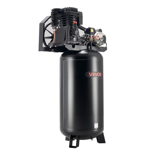 VEVOR 60 Gallons Heavy-Duty Air Compressor
|
8.9/10 | Buy | |
 Air Lift 16060 Air Compressor silver, 12V
|
8.6/10 | Buy | |
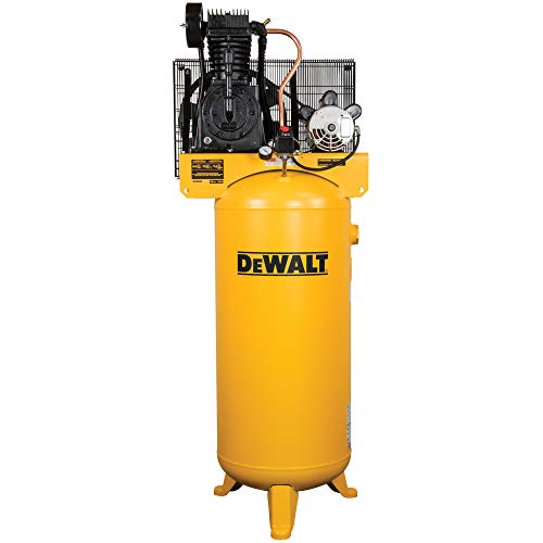 DEWALT 60-Gallon Stationary Vertical Air
|
8.4/10 | Buy |
Installing a stationary sixty-gallon air compressor provides a dependable pneumatic workstation for demanding air tools. An upright tank weighs several hundred pounds, generates mechanical vibration, and requires substantial electrical power during startup. Proper installation demands careful planning around foundation stability, electrical branch circuit capacity, vibration isolation, and distribution plumbing. Following structured installation procedures protects workshop infrastructure, preserves motor health, and delivers consistent airflow to demanding tools.
Site Selection and Environmental Clearances
Physical placement dictates how conveniently you can service and operate the compressor over its working life. An upright tank requires a level concrete floor capable of supporting substantial static weight and continuous operating vibrations. Maintain at least twelve to eighteen inches of perimeter clearance between the pump flywheel and nearby walls. Flywheel fan blades draw ambient air across the cylinders, and restricting this circulation causes excessive heat buildup and rapid oil breakdown.
Ambient air quality in your workshop directly influences internal pump longevity and intake filter life. Avoid positioning the compressor near high-dust woodworking stations, metal grinding benches, or paint overspray areas. Airborne particulates quickly clog intake filter elements and score polished cylinder walls, while solvent vapors introduce hazards near electrical switchgear. Enclosing the compressor in a ventilated utility space or plumbing the intake outside helps maintain clean operating conditions.
Floor Anchoring and Vibration Isolation
Stationary reciprocating compressors generate rhythmic harmonic vibrations that transmit directly into concrete slabs if not properly isolated. Bolting the tank legs directly against bare concrete creates intense structural stress along the mounting welds and tank base. Over extended cycling periods, this rigid metal contact can fatigue the steel, causing hairline cracks or foot failure. Placing oil-resistant elastomeric vibration pads beneath each mounting foot cushions the machine and prevents destructive harmonic transfer.
Anchoring the compressor prevents the vertical tank from creeping across the floor or tipping under high reciprocating loads. Mark the mounting hole positions onto the concrete slab through the pre-drilled holes in the tank feet. Drill the anchor holes using a hammer drill equipped with a masonry bit matched to heavy-duty wedge anchors. Clear all residual masonry dust from the holes before lowering the compressor feet over the anchor bolts.
Avoid tightening the anchor nuts down so hard that the rubber vibration isolators become fully compressed. Crushing the isolator pads completely destroys their elasticity and reintroduces rigid mechanical coupling to the floor. Tighten the anchor nuts until they contact the rubber bushing firmly, then secure them with a second jam nut. This fastening technique holds the tall tank securely in place while allowing the elastomeric material to absorb pump vibrations naturally.
Dedicated 240V Electrical Circuit Planning
Stationary sixty-gallon compressors generally operate on a 208-volt to 240-volt single-phase electrical supply. High-output induction motors rated between 3.7 and 5 horsepower pull considerable amperage, especially during initial motor startup. When evaluating motor electrical draw and circuit requirements, factor in starting inrush current, which can briefly exceed running current by several multiples. Undersized branch wiring causes severe voltage drop, leading to nuisance breaker trips and motor overheating.
Consult the motor data plate to determine continuous running amperage and manufacturer recommendations for circuit breaker sizing. A typical five-horsepower 240-volt motor commonly requires a dedicated 30-amp or 40-amp double-pole breaker paired with appropriate copper conductors. Install an external wall-mounted safety disconnect switch within sight of the compressor frame to provide immediate power isolation. Having a dedicated local disconnect switch allows you to cut electrical power safely before performing maintenance or oil changes.
Connect the wall disconnect switch to the pressure switch using flexible metallic conduit rather than rigid pipe. Vibrations from normal pump cycling will loosen rigid electrical conduit fittings over time and damage wire insulation. Inside the pressure switch enclosure, connect the two hot conductors to the primary line terminals and attach the ground wire securely. If your compressor incorporates an external magnetic starter, verify that all control circuit wiring matches the manufacturer schematic.
Flexible Discharge Lines and Distribution Plumbing
Connecting the compressor tank discharge port directly to rigid workshop piping causes premature joint failure. Reciprocating pumps create micro-vibrations that travel through the tank manifold during each compression stroke. Rigid pipe attached directly to the tank outlet experiences cyclic fatigue, which eventually cracks fittings and causes air leaks. Always install a flexible stainless steel braided jumper hose between the tank discharge port and the hard wall piping.
Select an air distribution piping material engineered specifically for high-pressure pneumatic workshop systems. Threaded schedule 40 black iron pipe and specialized modular aluminum tubing systems provide durable service without risk of shattering. Never use standard PVC or CPVC plastic plumbing for compressed air, as common plastics become brittle under pressure and burst into flying fragments. If soldering copper distribution lines, use type L or type K copper joined with lead-free solder capable of withstanding system pressure.
Pitch horizontal distribution headers slightly downward away from the compressor at a slope of roughly one inch per ten feet. This incline guides accumulated moisture toward drainage legs rather than allowing water to pool inside horizontal runs. Workstation drops should tee off from the top of the main header to prevent water from draining into tool couplers. Terminate every vertical drop with a manual ball valve at the base to serve as a moisture trap.
Downstream Air Treatment and Noise Management
Conditioning the air exiting your storage tank protects pneumatic equipment from water contamination and excessive wear. Atmospheric air contains humidity that condenses into liquid water inside the tank during the cooling phase of compression. Install a heavy-duty particulate filter and water separator on the wall immediately downstream from the flexible discharge hose. For sensitive operations like automotive spray painting, incorporate a secondary coalescing filter or desiccant dryer to remove oil aerosols and fine moisture vapors.
Downstream pressure regulation ensures pneumatic tools operate within their engineered pressure boundaries. Stationary sixty-gallon tanks store air at pressures between 145 and 175 PSI, which exceeds safe thresholds for most pneumatic hand tools. Mount an adjustable regulator downstream of your primary filters to dial working pressure back to ninety PSI for standard tools. Dual-gauge regulator assemblies allow you to monitor both supply header pressure and regulated working pressure at a glance.
Compressor noise levels can quickly become fatiguing inside enclosed garages or tight basement workshop areas. When evaluating compressor decibel levels, you will discover that intake pulsation creates much of the harsh sound produced by large pumps. Installing a metal-bodied intake filter muffler or silencer onto the pump intake port significantly dampens low-frequency intake noise. These threaded mufflers clean incoming ambient air while baffling intake sound pulses, creating a quieter shop environment without restricting airflow.
Lubrication Verification and Drive Belt Setup
Confirming proper pump lubrication before energizing the electric motor protects internal bearings from catastrophic dry starts. Many commercial compressors ship with testing oil or completely dry crankcases, requiring inspection prior to initial operation. Check the oil level through the transparent crankcase sight glass, ensuring the oil meniscus rests at the center of the indicator dot. Use only high-grade, non-detergent industrial compressor oil formulated specifically for reciprocating air compressors rather than standard automotive engine oil.
Check the mechanical alignment and tension of the drive belt connecting the motor pulley to the pump flywheel. Misaligned pulleys cause excessive belt friction, rapid groove wear, and elevated vibration levels during cycling. Place a straightedge across the pulley faces to verify that the motor pulley and flywheel sit parallel in the same plane. If the pulleys show misalignment, loosen the motor mounting fasteners to adjust the pulley position along the motor shaft.
Check drive belt tension by applying moderate thumb pressure at the midpoint of the belt span between the pulleys. A properly adjusted belt should deflect approximately one-half inch under moderate finger pressure without slipping on startup. If the belt feels loose, adjust the motor base positioning screws to slide the motor along its mounting slots. Once the tension is correct, torque down the motor bolts and reinstall the protective wire belt guard.
Zero-Pressure Pump Break-In Procedure
New reciprocating compressor pumps feature precision-machined piston rings and cast-iron cylinder walls that require gradual mechanical seating. Running a new pump immediately under high working pressure can glaze cylinder sleeves and cause poor ring seating. To complete a safe break-in, open the tank drain valve at the bottom of the vessel completely so that compressed air discharges freely into the room. This configuration allows the pump to cycle without generating internal tank pressure.
Energize the electrical disconnect switch to start the motor, allowing the compressor to run unpressurized for twenty to thirty minutes. The electric motor should spin smoothly, circulating crankcase oil across the cylinder walls, connecting rods, and crankshaft bearings. Listen closely for abnormal metallic knocks, loose pulleys, or unusual vibration during this initial run. Running the pump under zero pressure laps the piston rings against the honed cylinder walls, establishing optimal compression efficiency for long-term service.
After the break-in duration concludes, shut off the power switch and listen for the unloader valve operation. You should hear a distinct burst of air venting from the unloader valve line beneath the pressure switch. This venting depressurizes the pump cylinder heads, ensuring that the electric motor does not have to fight trapped head pressure during subsequent startups. If no air vents, inspect the unloader line and valve mechanism before putting the compressor into pressurized service.
Pressure Cycling and Safety Valve Testing
Close the tank drain valve firmly and energize the compressor to begin its first complete tank pressurization cycle. Watch the tank pressure gauge rise steadily until the machine reaches its factory cut-out threshold. Depending on whether your unit is a single-stage or two-stage machine, maximum pressure should settle between 145 and 175 PSI. Once cut-out pressure is achieved, the internal pressure switch contacts should open with a crisp click, cutting motor power immediately.
Perform a complete pneumatic leak check across all threaded fittings, drain valves, and manifold connections using a soapy water solution. Spray the solution over all pipe joints, check valve fittings, and pressure switch connections, looking for expanding bubbles. Escaping air indicates loose fittings that will cause the compressor to cycle repeatedly even when tools sit idle. If leaks appear, depressurize the tank completely before gently tightening the affected threaded connections with appropriate hand tools.
Verify the mechanical operation of the ASME safety relief valve while the storage tank remains pressurized. The safety relief valve protects the pressure vessel by opening automatically if the electrical pressure switch fails to shut off the motor. Put on safety glasses and hearing protection, then pull the manual ring on the safety valve outward briefly. A sharp blast of air should escape instantly, and the internal valve disc should snap shut tightly once you release the ring.
Preventative Maintenance and Daily Moisture Drainage
Establishing a regular maintenance routine keeps your stationary air compressor operating smoothly while protecting the steel tank against corrosion. Water condensation naturally settles at the base of the tank after every compression cycle, creating corrosive conditions if left unchecked. Open the bottom drain valve at the end of each work session to vent accumulated water and oily emulsion completely. Installing an easily accessible ball valve makes this daily draining chore quick and effortless.
Inspect crankcase oil clarity and level monthly, keeping the fluid level centered in the sight glass at all times. Perform an initial oil change after approximately one hundred operating hours to flush out break-in wear particles, followed by regular oil changes every three to six months. Clean the intake filter elements periodically to prevent dust accumulation from choking pump airflow. Taking these routine maintenance steps preserves pump volumetric efficiency and ensures your pneumatic system remains dependable for years.
Completing a clean, methodical installation gives your workshop a dependable compressed air source capable of handling demanding pneumatic tools. Isolating vibration with elastomeric pads, wiring a dedicated 240-volt circuit, and decoupling piping with a flexible jumper line prevents common equipment failures. Follow manufacturer guidelines, maintain daily condensation draining routines, and respect electrical and pneumatic safety boundaries to keep your stationary compressor running reliably throughout its working life.
About the author
Clint DeBoer is an experienced tool-industry specialist with decades of involvement in technical media, hands-on product evaluation, and testing methodology. His focus on performance, practical usability, and data-driven comparisons makes his expertise highly relevant to professional air compressors, pneumatic tools, and workshop equipment.