
How to Keep Water out of Air Compressor Tank: Practical Prevention Guide for 2026
Learn how to keep water out of air compressor tank using extended drain kits, automated solenoid valves, and line filters to prevent tank rust and tool damage in October 2026.
 By Bob Beacham
Updated October 8, 2026
By Bob Beacham
Updated October 8, 2026

Atmospheric air naturally carries suspended water vapor that rapidly condenses into liquid inside a compressed air storage vessel. When a reciprocating pump draws in ambient air and pressurizes it past 100 PSI, the intense thermal spike forces moisture out of suspension as the air cools against steel walls. Knowing how to keep water out of air compressor tank reservoirs is essential for preventing aggressive internal rust that weakens pressure vessel walls over time. Without proper moisture mitigation, accumulated liquid pools at the base of the tank, reducing usable air volume and threatening pneumatic tools with rust and sludge. Following a reliable compressor tank draining routine helps protect both your storage vessel and downstream air delivery lines.
Water trapped inside an air receiver does not simply stay dormant at the bottom of the tank. High-velocity air currents push rust-laden moisture through whip hoses directly into sensitive pneumatic impact wrenches, finish nailers, and paint spray guns. Selecting the right combination of extended manual drain valves, automated electronic purge solenoids, and inline moisture traps stops liquid accumulation before it ruins expensive pneumatic equipment. Implementing these upgrades creates a reliable defense against corrosion while ensuring that your workshop delivers clean, dry pneumatic power for every project.
| Award | Product | ACR Score About ACR ScoreThe ACR Score is our own rating from 0 to 10, based on performance, design and build, ease of use, and value. It reflects independent research and is never influenced by manufacturers, retailers, or affiliate commissions. Learn more › | |
|---|---|---|---|
| Best Overall |
JOROY 10-Inch Extended Air Compressor Tank Drain
|
9.2/10 | Buy |
| Best Value |
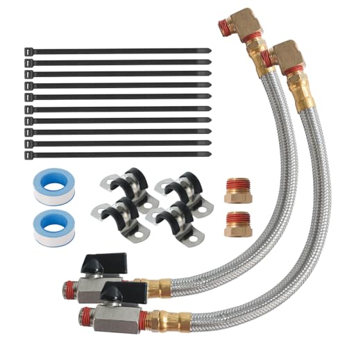 2 Pack Extended Tank Drain Valve Assembly Kit
|
9.1/10 | Buy |
| Best Budget |
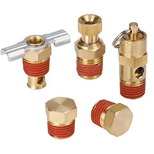 Hromee 5 Piece 1/4 Inch Compressor Air Tank Port
|
8.9/10 | Buy |
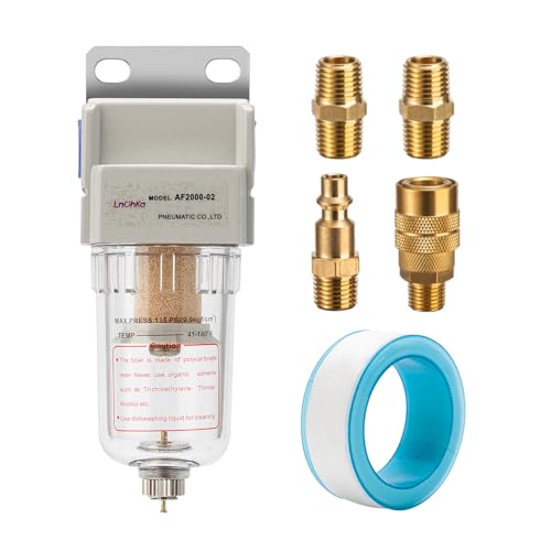 LNCHKA Air Compressor Water Separator
|
8.9/10 | Buy | |
| Best Premium |
 UNOX Electronic Drain Valve for Air Compressor
|
8.9/10 | Buy |
 Hromee Automatic Air Compressor Tank Drain Valve
|
8.6/10 | Buy | |
 Extended Tank Drain Valve Assembly Kit for Air
|
8.3/10 | Buy | |
 Automatic Electronic Tank Drain Kit
|
8.3/10 | Buy | |
 1/4" NPT Timer Operated Compressor Air Drain
|
8.3/10 | Buy | |
 QWORK Electronic Drain Valve
|
8.0/10 | Buy |
Practical Strategies for Eliminating Condensation in Air Tanks
Moisture accumulation inside a compressed air receiver is an unavoidable physical consequence of ambient air compression. When air is drawn into a pump cylinder and compressed to high pressure, its temperature climbs significantly, holding vapor until it reaches the storage tank. As this heated air cools against the interior steel walls, water vapor condenses into liquid that collects at the lowest point of the tank. Managing this condensation requires a layered strategy that combines accessible tank drainage, automated purging mechanisms, and smart air distribution piping.
The Thermodynamics of Condensation in Compressed Air Receivers
Every cubic foot of ambient atmospheric air contains a specific percentage of relative humidity in the form of invisible water vapor. When a compressor pump draws in ten cubic feet of atmospheric air and packs it into one cubic foot of tank space, it also concentrates that water vapor tenfold. The mechanical heat generated during the compression stroke temporarily keeps this vapor in an expanded gaseous state while inside the pump head. Once that compressed air enters the cooler steel receiver tank, the ambient metal acts like a condenser, dropping the air temperature below its pressure dew point.
Liquid water immediately precipitates onto the tank walls and runs downward into the bottom sump. If this pooling liquid remains inside the pressure vessel, oxygen and standing water interact with unprotected carbon steel to produce iron oxide. Over time, internal rust flakes peel away and settle into a gritty sludge that clogs drain ports and fouls downstream fittings. Severe corrosion also reduces the structural thickness of the tank wall, raising serious safety concerns under high cyclical pressure.
Water accumulation also robs the compressor of its intended air storage capacity. A receiver tank that holds two gallons of stagnant water loses two gallons of usable pneumatic buffer space, forcing the pump motor to cycle much more frequently. Frequent motor cycling causes premature wear on magnetic starters, pressure switches, and capacitor assemblies while increasing electrical energy consumption. Preventing liquid buildup protects the physical tank, stabilizes pneumatic pressure delivery, and prolongs the service life of the entire compressor package.
Upgrading to Accessible Extended Manual Drain Assemblies
Most consumer and commercial air compressors ship from the factory with inexpensive threaded thumb petcocks or winged brass drain cocks mounted directly beneath the tank. These small valves sit only an inch or two above the shop floor, making them difficult to reach, awkward to grip, and prone to painful knuckle scrapes. Because these stock petcocks require substantial effort to twist, many operators neglect daily draining entirely. Stiff winged drain cocks also tend to seize up quickly when grit and scale lodge within their fine brass threads.
Installing an extended drain assembly fundamentally changes how often an operator purges accumulated water. Extended kits, such as those produced by JOROY and SUNROAD, utilize a flexible braided stainless steel hose rated for 175 PSI working pressure and 475 PSI burst thresholds. One end connects to the bottom tank port using a 1/4-inch brass elbow fitting, while the opposite end brings the valve out to an easily accessible spot on the compressor frame. The braided steel jacket protects the internal tubing from abrasion and kinks, ensuring reliable operation in demanding shop environments.
At the accessible end of the extension hose sits a smooth quarter-turn brass ball valve equipped with an ergonomic lever handle. Opening a quarter-turn ball valve takes less than a second and requires only one hand, removing any friction or hesitation from the daily maintenance routine. The full-port internal ball design provides a clear, unrestricted exit pathway that quickly flushes rust flakes, sludge, and liquid without jamming. Pre-applied thread sealant on brass elbow fittings helps ensure an airtight seal during installation without requiring extra liquid thread compounds.
Automating Moisture Purging with Timed Electronic Drain Solenoids
In high-production shops or busy garages, relying on manual memory to drain receiver tanks every single day can lead to missed maintenance cycles. Electronic timed drain valves provide a fully automated solution by purging accumulated moisture on a precise, repeatable schedule. Assemblies manufactured by UNOX, Hromee, and QWORK combine a solid-state electronic timer with a heavy-duty direct-acting solenoid valve body. Powered by standard 110-volt or 120-volt alternating current, these systems automatically open the discharge port at predetermined intervals to blast out moisture.
Modern electronic auto-drains feature dual adjustment knobs that allow complete customization of the discharge cycle. The off-cycle interval can typically be adjusted from thirty seconds up to forty-five or fifty minutes, while the on-cycle discharge duration ranges between half a second and ten seconds. Setting the timer to fire for two or three seconds every thirty minutes keeps the receiver sump completely dry during intensive spraying or sanding operations. An integrated manual test button lets operators verify solenoid operation and clear residual moisture instantly without altering the timer dials.
Durability in harsh workshop environments depends heavily on construction quality and debris filtration. Commercial electronic drain valves feature robust brass bodies rated up to 232 PSI or higher, along with IP65-rated enclosures that resist workshop dust and ambient water splashes. Sludge and scale carried by discharging moisture can easily foul delicate solenoid plungers, which is why top-tier assemblies incorporate an integrated ball valve strainer upstream of the valve seat. This mesh strainer captures scale before it enters the magnetic valve chamber, while the ball valve allows easy isolation during routine strainer cleaning.
Installing Point-of-Use Water Separators and Line Filters
Even with an aggressive tank drainage routine, compressed air exiting the receiver tank still carries microscopic moisture droplets and high vapor humidity. Installing an inline particulate filter and water separator, such as the LNCHKA AF2000-02 model, captures lingering moisture before it reaches delicate pneumatic equipment. These compact units utilize a 1/4-inch NPT connection and are rated for working pressures up to 145 PSI, delivering clean airflow for systems rated up to 18 SCFM. A transparent polycarbonate filter bowl allows operators to monitor water accumulation at a quick glance during active shop work.
Inside the separator body, incoming air is forced through a directional baffle that creates a high-speed centrifugal vortex. This swirling motion flings heavier liquid droplets and oil mists against the outer bowl walls, where they slide down into a quiet collection zone beneath a baffle plate. The air then passes through a porous 5-micron sintered brass filter element that traps solid particulates, pipe scale, and rust grains. A manual push-drain or semi-automatic float drain at the bottom of the bowl allows accumulated water to be evacuated with minimal effort.
Placement along the pneumatic supply line plays a critical role in filter efficiency. Mounting a water separator directly onto the compressor discharge port is a common mistake because the air at that point is still too hot for vapor to condense into droplets. Placing the filter at least twenty to thirty feet downstream allows the air to cool sufficiently, ensuring that vapor condenses into liquid water that the 5-micron brass element can actually capture. For critical applications like automotive painting or plasma cutting, pairing a centrifugal separator with a secondary desiccant dryer yields clean, dry results.
Optimizing Workshop Plumbing and Air Line Drop Geometry
Workshop air distribution piping serves as an extended cooling system that can either assist in moisture removal or dump gallons of water into your tools. Running flexible rubber hoses across the floor creates low spots where liquid collects, eventually surging forward into air tools in violent bursts. Permanent hard lines made of copper or specialized modular aluminum piping provide a smooth, rigid conduit that promotes gradual air cooling and controlled moisture runoff. Pitching the main overhead distribution lines slightly backward toward the compressor allows condensed water to drain by gravity back into a dedicated collection point.
Every workstation feed line coming off the main header should utilize an overhead loop or gooseneck connection rather than tapping directly into the bottom of the pipe. Tapping off the top of the header prevents water pooling along the pipe invert from draining down into tools. Each drop line should extend downward past the tool regulator connection to form a dedicated vertical drip leg. Capping the bottom of this drip leg with a manual ball valve or automatic drain allows liquid to settle harmlessly out of the main airflow stream.
High-volume shops running continuous-demand equipment often benefit from expanding their storage capacity. If you are planning an extensive workshop air distribution layout, plumbing an auxiliary air tank provides extra surface area that cools hot air and captures additional condensation before it enters distribution drops. Auxiliary receiver tanks act as massive moisture drop legs when plumbed correctly with dedicated bottom drains. Purging both the primary and auxiliary receiver vessels ensures consistent, dry pneumatic delivery across multi-station pneumatic setups.
Controlling Ambient Workshop Humidity and Compressor Placement
The ambient air surrounding your compressor pump determines the total moisture volume introduced into the pneumatic system. Positioning an air compressor in a damp, poorly ventilated basement or directly beside an open wash bay forces the intake pump to ingest humid air constantly. Drawing intake air from a cooler, drier location substantially reduces the rate of water condensation inside the receiver tank. In humid summer climates, operating an industrial dehumidifier in the compressor room significantly lowers incoming moisture levels.
Ambient temperature also influences how efficiently compressor intercoolers and aftercoolers drop air temperatures before storage. Compressors tucked into tight, unventilated corners operate at elevated pump head temperatures, which delays condensation until the air travels far down your workshop hoses. Maintaining at least twelve to eighteen inches of open clearance around cooling fans and cast-iron pump fins keeps operating temperatures within manufacturer limits. Cooler pump operation leads to earlier condensation inside the receiver tank where it can be purged easily through the bottom drain.
Proper pump lubrication also impacts internal temperature management and moisture resistance inside the crankcase. Following a structured compressor pump oil maintenance schedule ensures that non-detergent synthetic compressor oil lubricates pistons and cylinders without breaking down under heat. When oil breaks down or absorbs ambient moisture, it forms an emulsified sludge that harms pump components and contaminates discharge air. Clean oil maintains tight piston ring seals, reducing excessive blow-by that carries vapor and oil aerosol into the air receiver.
Distinguishing Between Clean Condensate and Contaminated Sludge
Inspecting the liquid discharge during daily purging provides valuable diagnostic clues about the health of your pneumatic system. Clean, clear water indicates normal atmospheric condensation with minimal internal tank corrosion or pump seal degradation. A dark reddish-brown liquid signifies that internal rust is actively flaking away from the carbon steel vessel walls, highlighting an urgent need for more frequent drainage routines. If the discharge appears milky or frothy, oil is actively bypassing the pump rings and mixing with accumulated condensate.
Oil-lubricated pumps naturally pass minute amounts of oil vapor, but excessive emulsification indicates worn piston rings, damaged reed valves, or overfilled crankcase sumps. Milky condensate can quickly clog downstream pneumatic regulators and ruin sensitive paint finishes by depositing silicone and hydrocarbons on workpieces. Installing an oil-coalescing filter directly downstream of your particulate separator helps trap emulsified mists before they enter supply hoses. Addressing oil blow-by early prevents sticky sludge from accumulating inside automated drain solenoids and stalling internal valve plungers.
Safe Tank Depressurization and Drain Maintenance Checklist
Working around high-pressure air receiver tanks requires strict adherence to workshop safety protocols. Never attempt to remove or unthread a tank drain valve, elbow fitting, or inspection plug while the receiver contains pressurized air. Always disconnect the compressor from its electrical supply, open the drain valve slowly to vent remaining pressure down to zero PSI, and pull the ASME safety relief valve ring to verify zero pressure. Wearing protective safety glasses and hearing protection shields operators from high-decibel air blasts and flying rust particulates during blowdown procedures.
Establishing a consistent inspection checklist keeps automated and manual drainage systems operating at peak reliability. Inspect flexible braided steel lines monthly for signs of outer wire fraying, kinking, or leakage around threaded brass bushings. Clean the wire mesh screen inside electronic drain strainers quarterly to prevent compressed rust flakes from locking solenoid seats open. Regularly cycling the manual test button on electronic timers verifies that electrical power is reaching the solenoid coil and that the internal plunger moves freely.
Protecting your air compressor receiver tank from internal rust and water buildup requires a proactive, layered defense. Combining an accessible quarter-turn extended drain valve or an automated electronic timer with proper line filtration stops liquid from reaching expensive tools. Positioning drop legs correctly and keeping workshop ambient humidity under control further enhances overall pneumatic air quality. Implementing these proven moisture management methods ensures that your workshop equipment delivers reliable, moisture-free performance while keeping your air tank safe for years to come.
About the author
Bob Beacham is an experienced tools and workshop writer with deep knowledge of power equipment, mechanical systems, and practical DIY applications. His coverage of air compressors, welding equipment, saws, and workshop tools helps translate technical specifications into useful guidance for homeowners and serious DIYers.