
How to Make a Gas Powered Air Compressor: Practical Guide for 2026
Learn how to make a gas powered air compressor with this practical engineering guide covering pilot valves, engine sizing, and safety for October 2026.
 By Bob Beacham
Updated October 8, 2026
By Bob Beacham
Updated October 8, 2026

Remote jobsites and mobile service trucks frequently lack reliable electrical service, making standard high-draw electric compressors impractical for heavy pneumatic tools. Operating high-demand equipment like framing nailers, impact wrenches, and paint sprayers in off-grid environments requires independent mechanical power. Understanding how to make a gas powered air compressor allows contractors and mechanics to harness small four-stroke engines to drive heavy-duty cast iron pumps. This mechanical configuration eliminates electrical breaker tripping while delivering continuous high-volume airflow wherever work demands.
Constructing or configuring an engine-driven pneumatic rig requires careful component matching, proper pulley ratios, and specialized unloader valves that manage continuous engine rotation. Choosing between custom fabrication and purpose-built factory machines often depends on technical familiarity with belt alignment, safety valves, and engine governor linkages. Investigating oil-lubricated and oil-free air compressor differences also helps determine whether a splash-lubricated cast iron pump will endure the intense duty cycle demands of field service. By focusing on verified horsepower ratings, ASME safety parameters, and realistic airflow delivery, builders can assemble a durable mobile power source tailored to demanding pneumatic tools.
| Award | Product | ACR Score About ACR ScoreThe ACR Score is our own rating from 0 to 10, based on performance, design and build, ease of use, and value. It reflects independent research and is never influenced by manufacturers, retailers, or affiliate commissions. Learn more › | |
|---|---|---|---|
| Best Overall |
9 Gallon Twin-Tank Gas Powered Air Compressor
|
9.2/10 | Buy |
| Best Value |
 HPDMC 6.5HP Gas Powered Air Compressor 12CFM
|
9.2/10 | Buy |
 XtremepowerUS 13.0HP Horizontal Air Compressor
|
9.2/10 | Buy | |
| Best Budget |
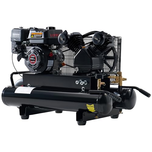 Albott 6.5HP Gas Powered Air Compressor 8 Gallon
|
9.1/10 | Buy |
 VEVOR 9 Gallon Twin-Tank Gas Powered Air
|
8.9/10 | Buy | |
| Best Premium |
 HPDMC 13HP Gas Powered Air Compressor, 3-Cylinder
|
8.8/10 | Buy |
 VEVOR 13.2 Gallon Gas Powered Air Compressor
|
8.6/10 | Buy | |
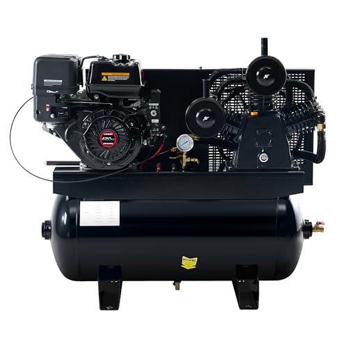 Albott 13HP Gas Air Compressor 30 Gallon
|
8.6/10 | Buy | |
 VEVOR 15HP Gas Powered Air Compressor
|
8.6/10 | Buy | |
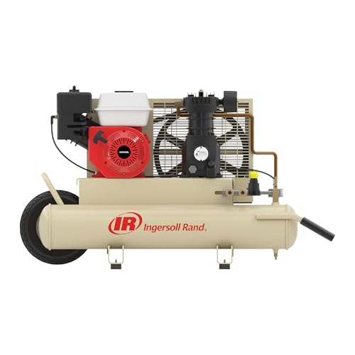 Ingersoll Rand SS3J5.5GH-WB 5.5 HP Gas Air
|
8.3/10 | Buy |
Engineering and Assembling a Gas-Powered Air Compressor System
Understanding Continuous-Run Pneumatic Mechanics
Electric air compressors typically rely on pressure switches that disconnect electrical power to stop the motor when the tank reaches maximum pressure. Internal combustion engines cannot be repeatedly started and stopped each time receiver pressure cycles without quickly destroying the starter motor and draining battery reserves. Gas-powered air compressors solve this mechanical challenge by running continuously while utilizing a pneumatic pilot unloader valve to manage compression cycles. When receiver tank pressure reaches the cut-out threshold, the pilot valve vents discharge air or holds the intake valves open to eliminate compression resistance.
This continuous-run design allows the small utility engine to spin freely during unloaded intervals without building excessive tank pressure. As pneumatic tools consume stored air and tank pressure drops to the calibrated cut-in point, the pilot valve shifts position to restore normal compression. The cylinder head valves begin capturing atmospheric air again, forcing compressed volume past the reed valves and into the receiver tank. Mastering this continuous unloader cycle is the most essential principle when determining how to configure an engine-driven pneumatic power system.
Matching Engine Horsepower to Pump Air Delivery Requirements
Selecting the appropriate four-stroke utility engine requires calculating the mechanical workload imposed by the reciprocating pump cylinders under peak pressure. A reliable mechanical rule of thumb for pneumatic systems dictates approximately one horsepower of gas engine output for every one to two cubic feet per minute of delivered air at ninety PSI. Portable wheelbarrow configurations featuring engines rated from 5.5 to 6.5 horsepower typically drive single-stage twin-cylinder pumps delivering between 9 and 12 CFM. Commercial truck-mount units with 13 to 15 horsepower engines power three-cylinder pumps that deliver between 18 and 44 CFM to handle heavy industrial air tools.
Undersizing the engine creates severe mechanical strain, leading to engine stalling, overheating, and premature cylinder wall wear whenever tank pressure nears maximum levels. Oversizing the engine adds unnecessary carry weight, higher fuel consumption, and severe vibration that can fatigue structural frame welds. Builders must evaluate whether their pneumatic tools require continuous air volume, such as rotary sanders or paint sprayers, or intermittent delivery like framing nailers. Matching true continuous engine torque to pump displacement prevents engine RPM drop during demanding compression strokes.
Calculating Pulley Ratios and Target Pump Speeds
Small utility gasoline engines operate most efficiently at a governed speed of approximately 3,600 revolutions per minute under load. Reciprocating cast iron compressor pumps require much slower operational speeds, generally between 800 and 1,200 RPM, to prevent reed valve destruction and oil breakdown. Connecting an engine directly to a compressor pump without speed reduction would quickly destroy the pump bearings and piston wrist pins. Calculating the correct pulley ratio ensures the pump operates within its intended design RPM while utilizing the engine torque curve effectively.
To determine the required pulley dimensions, multiply the engine crankshaft RPM by the drive pulley diameter and divide that number by the target pump RPM. For example, installing a 4-inch drive pulley on a 3,600 RPM engine paired with a 12-inch pump flywheel results in an operating speed of exactly 1,200 RPM. The pump flywheel also serves as an essential cooling component, featuring cast iron fan blades that blow cool air across the cylinder head fins. Using durable B-section V-belts or matched twin A-section belts ensures positive torque transfer without slipping under peak compression cycles.
Configuring the Pilot Unloader and Throttle Idle Control
The pilot unloader valve acts as the central pneumatic regulator for the entire gas-powered compressor assembly. Connected directly to the receiver tank, this specialized brass valve monitors tank pressure and actuates an auxiliary air circuit when line pressure hits the cut-out threshold. Instead of interrupting engine ignition, the pilot valve redirects high-pressure air through dedicated signal tubing to unloader actuators located on the pump cylinder heads. These unloader devices mechanically hold the intake reed valves open, allowing pistons to cycle without compressing air.
Simultaneously, the pilot unloader sends a pneumatic signal to an engine throttle control cylinder, commonly referred to as a bullseye idle-down control. This miniature air piston pushes against the engine governor linkage, dropping engine speed down to idle while the pump freewheels. Reducing engine RPM during unloaded intervals conserves fuel, lowers exhaust emissions, and dramatically reduces noise on active jobsites. When downstream tool consumption causes tank pressure to drop to the cut-in threshold, the pilot valve exhausts signal pressure, letting the engine accelerate to full speed before compression resumes.
Fabricating a Rigid Foundation and Aligning Drive Belts
Single-cylinder utility engines produce substantial harmonic vibration that can quickly loosen fasteners and crack lightweight structural frames. Fabricating a solid mounting deck from quarter-inch steel plate provides the structural rigidity necessary to stabilize both the engine block and the pump crankcase. Slotted mounting holes machined into the engine base plate allow precise lateral adjustment for setting drive belt tension. Incorporating heavy-duty rubber vibration dampeners between the mounting deck and receiver tank helps isolate structural welds from cyclic combustion fatigue.
Precise belt alignment is vital to prevent premature belt shredding, pulley groove wear, and crankshaft seal leakage. Builders should use a precision straightedge or laser alignment tool pressed across both pulley outer faces to verify that the engine sheave and pump flywheel sit perfectly coplanar. Belt tension should allow roughly one-half inch of deflection under moderate finger pressure midway between pulleys. Installing a sturdy steel wire or perforated sheet-metal belt guard protects operators from high-speed rotating pinch points while permitting cooling airflow to reach the pump.
Plumbing Receiver Tanks and Installing ASME Safety Valves
Pressurized air storage tanks contain immense potential energy and require strict adherence to certified manufacturing standards. A gas compressor project must utilize an ASME-certified pressure vessel rated for a working pressure equal to or exceeding the maximum pilot valve setting. Connecting the pump discharge port to the receiver tank requires high-temperature copper tubing or braided stainless steel flex lines to endure intense heat. Installing a heavy brass one-way check valve directly into the tank inlet port prevents stored air from bleeding backward into the pump heads during idle cycles.
Every pneumatic receiver tank must include a functioning ASME-rated safety relief valve set slightly above the pilot cut-out pressure. If the pilot unloader fails to actuate or signal tubing becomes clogged, this mechanical pop-off valve automatically vents excess tank pressure to prevent catastrophic tank rupture. Builders must never bypass, plug, or alter the factory calibration of this safety relief valve. Testing the relief valve ring periodically verifies that the internal spring and sealing disc remain free from corrosion and carbon debris.
Managing Tank Condensation and Downstream Air Delivery
Atmospheric air contains water vapor that rapidly condenses into liquid water as hot compressed air cools against the interior walls of the receiver tank. Accumulated tank moisture reduces usable air storage volume, accelerates interior steel corrosion, and travels downstream into expensive pneumatic tools. Installing an accessible quarter-turn brass ball valve at the bottom of the receiver tank ensures quick, regular moisture purging after every work session. Threaded needle petcocks often become seized with rust particles, making a lever-operated brass ball valve far more reliable for long-term maintenance.
Delivering clean, stable airflow to field tools also depends on quality distribution plumbing and filtration accessories. Connecting the tank manifold to durable air compressor hose options reduces dynamic pressure drop across long jobsite distances. High-volume pneumatic equipment like framing nailers, impact wrenches, and texture guns require unrestricted internal hose diameters to prevent power loss. Incorporating an in-line water separator and pressure regulator ensures sensitive air tools receive consistent, moisture-free airflow during demanding operating schedules.
Executing Initial Zero-Pressure Break-In and Tuning
Before subjecting a newly assembled gas-powered compressor to full operating pressure, the system must undergo a dedicated mechanical break-in procedure. Both the engine crankcase and the compressor pump crankcase must be filled with their respective manufacturer-recommended lubricants. Compressor pumps typically require non-detergent ISO 68 or ISO 100 compressor oil to prevent foaming and internal valve carbonization. Running the engine at moderate speed with the tank drain valve wide open allows the pump pistons, rings, and rod bearings to burnish without compression resistance.
After running unloaded for twenty to thirty minutes, close the drain valve to observe the initial tank pressurization cycle. Monitor the line pressure gauge closely to verify that the pilot unloader valve trips cleanly at the predetermined cut-out threshold. Observe whether the throttle control linkage successfully reduces engine RPM to an idle state once the pilot valve actuates. Spraying a soapy water solution across all threaded fittings, check valve connections, and flare joints allows builders to identify and seal pneumatic leaks before putting the compressor into regular service.
Evaluating DIY Assembly Versus Factory Manufactured Equipment
Building a gas-powered air compressor from scratch provides complete customization over pump capacity, engine brand, and tank orientation. However, sourcing individual commercial components like cast iron pumps, utility engines, pilot valves, throttle actuators, and ASME tanks often results in significant cumulative costs. Manufactured units from established pneumatic brands come fully engineered with balanced components, EPA-certified engines, and factory-matched belt drive systems. When assessing equipment longevity, consulting an evaluating oil-free compressor longevity overview explains why heavy cast iron splash-lubricated pumps remain the gold standard for continuous field duty.
Factory-built wheelbarrow compressors and stationary horizontal truck-mount platforms offer integrated structural warranties and certified road-ready mounting brackets. Pre-assembled units eliminate the risk of pulley misalignment, improper engine governor calibration, or unsafe unloader valve plumbing. Mobile service mechanics and construction crews often find that factory equipment delivers proven reliability right out of the crate. Builders must carefully weigh the satisfaction of custom fabrication against the time, expense, and strict safety standards required for high-pressure pneumatic machinery.
Operational Maintenance for Long-Term Field Reliability
Routine operational maintenance is essential to keep an engine-driven air compressor operating safely in harsh jobsite conditions. Engine oil, spark plugs, and intake air filters require inspection and servicing at regular operating intervals to prevent power loss under heavy pump loads. Checking pump oil clarity through the crankcase sight glass ensures bearings remain lubricated with clean, moisture-free non-detergent oil. Inspecting drive belt tension and examining flexible discharge lines for heat embrittlement prevents unexpected breakdowns in remote work locations.
Daily procedures should always include depressurizing the receiver tank and opening the bottom drain valve to expel collected water and oil vapor. Checking the smooth operation of the pilot unloader valve and safety relief valve ensures the continuous-run system regulates pressure correctly without dangerous pressure spikes. Storing the equipment in a dry, ventilated area protects both the small engine fuel system and the cast iron pump cylinders from internal moisture damage. Proper mechanical care and sound operating habits guarantee dependable, high-volume pneumatic power whenever off-grid projects require mobile compressed air.
About the author
Bob Beacham is an experienced tools and workshop writer with deep knowledge of power equipment, mechanical systems, and practical DIY applications. His coverage of air compressors, welding equipment, saws, and workshop tools helps translate technical specifications into useful guidance for homeowners and serious DIYers.