
How to Add Tank to Air Compressor: Setup and Plumbing Guide for 2026
Learn how to add tank to air compressor systems safely in October 2026 to expand air storage, stabilize pressure, and support high-draw air tools.
 By Clint DeBoer
Updated October 8, 2026
By Clint DeBoer
Updated October 8, 2026

Running air tools like dual-action sanders, high-torque impact wrenches, or paint sprayers on a compact compressor often leads to frustrating line pressure drops and rapid motor cycling. When an undersized air tank runs out of stored air volume, pneumatic tools sputter and stall while the electric motor strains to keep up. Learning how to add tank to air compressor setups provides an effective way to expand your available air storage buffer without buying a completely new machine. An auxiliary air receiver tank acts as an energy reservoir, holding high-pressure air that cushions sudden demands from high-draw pneumatic equipment.
Plumbing an additional air reservoir requires careful attention to pneumatic plumbing fittings, operating pressure limits, and essential safety devices. Installing proper components like an ASME safety relief valve, a heavy-duty manifold, and an accessible quarter-turn tank drain valve ensures that your expanded air system runs efficiently and safely. While an extra tank will not increase your compressor pump CFM output, it significantly prolongs tool runtimes during intermittent bursts and smooths out pressure fluctuations. By understanding the mechanical connections and required fittings, you can easily plumb an auxiliary tank into your garage or workshop air delivery line.
| Award | Product | ACR Score About ACR ScoreThe ACR Score is our own rating from 0 to 10, based on performance, design and build, ease of use, and value. It reflects independent research and is never influenced by manufacturers, retailers, or affiliate commissions. Learn more › | |
|---|---|---|---|
| Best Overall |
Air Tank Repair Kit, SUNROAD this kit Including
|
9.2/10 | Buy |
| Best Budget |
 4Pcs 2 Sizes Brass Air Inflator Adapter
|
9.1/10 | Buy |
| Best Premium |
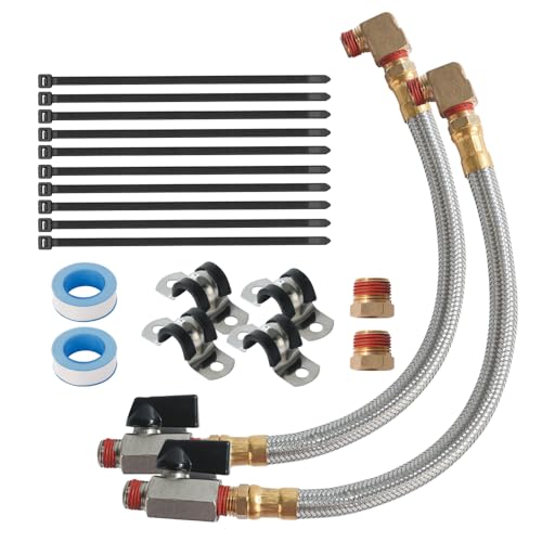 2 Pack Extended Tank Drain Valve Assembly Kit
|
9.1/10 | Buy |
 QWORK 2 Pack Extended Tank Drain Valve Assembly
|
9.1/10 | Buy | |
| Best Value |
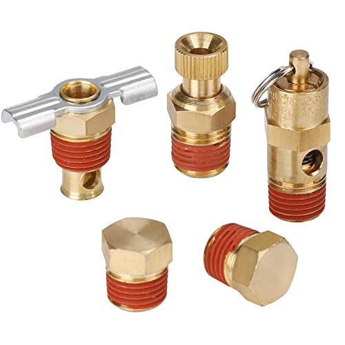 Hromee 5 Piece 1/4 Inch Compressor Air Tank Port
|
8.9/10 | Buy |
 LUMITECO Quick Connect Tire Chuck Hose
|
8.8/10 | Buy | |
 Hromee Air Tank Manifold Tool with Fill Port
|
8.4/10 | Buy | |
 Extended Tank Drain Valve Assembly Kit for Air
|
8.3/10 | Buy | |
 QWORK Extended Tank Drain Valve Assembly Kit
|
7.8/10 | Buy | |
 New Air Compressor Tank Manifold w/Built in Ball
|
7.8/10 | Buy |
Plumbing and Operating an Auxiliary Air Compressor Tank
Adding an auxiliary air receiver tank to an existing compressor system expands stored pneumatic volume to help power air-demanding tools. While a secondary tank creates a larger reserve of compressed air, it must be plumbed with proper pressure ratings and dedicated safety devices. Following correct plumbing practices ensures that your expanded system delivers smooth line pressure without placing unsafe strain on pneumatic fittings or electrical components. Understanding how stored air behaves under load allows you to configure a setup that matches your specific tool demands.
Understanding Buffer Storage Volume Versus Pump CFM Delivery
Connecting an extra tank to an air compressor alters air volume capacity rather than pump output. Many air tool operators mistakenly assume that doubling tank capacity will allow a small compressor to run high-draw tools continuously. In reality, compressor air delivery is governed strictly by the pump displacement, measured in cubic feet per minute at 90 PSI. An auxiliary tank provides a larger buffer of stored energy, allowing tools like impact wrenches or framing nailers to run longer before line pressure collapses.
Once that expanded buffer is depleted, the compressor pump must run longer to recover back to its cut-off pressure threshold. If you run a continuous-demand tool such as a rotary sander or HVLP paint sprayer, the pump will eventually fall behind regardless of tank size. The primary mechanical advantage of an auxiliary tank is absorbing short, intense air consumption spikes without triggering an immediate pressure drop. Understanding this balance between stored volume and pump displacement helps you set realistic expectations for your workshop air system.
Choosing Between Regulated Tool Line and Unregulated Tank Plumbing
Pneumatic systems can integrate an auxiliary tank using two distinct plumbing strategies depending on the intended workflow. The first method connects the secondary tank directly to the primary tank manifold before the pressure regulator, storing air at full cut-out pressure. This unregulated setup maximizes total stored energy because the secondary vessel holds the same 125 to 150 PSI as the primary compressor tank. Storing air at maximum pressure creates a deep reservoir that cushions air tools when demand spikes occur.
The second method plumbs the auxiliary tank downstream from the primary regulator, keeping the secondary tank at working tool pressure, such as 90 PSI. Storing air at regulated pressure reduces the mechanical stress on secondary hoses and fittings, making it convenient for portable carry tanks. However, this approach limits the total volume of usable air because the pressure differential between the tank and the tool is much smaller. Most permanent workshop installations benefit from plumbing the secondary receiver tank directly into the unregulated high-pressure side of the compressor.
Core Plumbing Hardware and Manifold Configurations
Building a reliable auxiliary tank connection requires heavy-duty brass fittings and purpose-built air manifolds. Many compressor tanks feature standard 1/2-inch male NPT ports that accept sturdy replacement manifold assemblies. A proper brass manifold with an aluminum shut-off knob provides dedicated connection points for essential pneumatic components. These configurations typically feature a 1/2-inch MNPT inlet for the tank bung, a 1/4-inch FNPT outlet for air delivery lines, and a 1/8-inch FNPT port for monitoring internal tank pressure. Using dedicated ports prevents dangerous overcrowding of fittings and ensures clean routing for supply lines.
Solid brass construction prevents thread corrosion and galling, which commonly occurs when mixing mismatched steel and aluminum components in humid air environments. High-quality manifold assemblies often feature integrated shut-off valves that let you isolate the auxiliary tank when portable carry use is required. If you are retrofitting an older portable carry tank as your secondary reservoir, you may also need male thread brass inflator adapters with standard Schrader valve cores. Incorporating precision-machined NPT tapered threads ensures a snug mechanical fit that minimizes minor air seepage under vibration. Matching thread sizes accurately across all adapters maintains full pneumatic flow without creating unnecessary bottlenecks.
Essential Overpressure Protection and Safety Relief Valves
Every pressurized vessel in a workshop pneumatic system must have its own dedicated safety relief valve. When you plumb two tanks together, you cannot rely solely on the primary compressor pressure switch or its single factory relief valve. If an isolation valve between the tanks is closed while air is introduced, or if an obstruction occurs in the interconnecting line, an unprotected secondary tank can over-pressurize and rupture. A brass safety valve with a stainless steel spring and pull ring provides essential mechanical fail-safe protection. Installing this valve directly on the secondary tank bung ensures constant protection regardless of line valve positions.
Most portable air tanks and secondary workshop vessels utilize safety pop-off valves calibrated to open between 125 and 150 PSI. The maximum pressure rating of your relief valve should never exceed the working pressure stamped on the secondary tank data plate. Safety valves, such as 140 PSI brass models with manual override pull rings, release excessive volume rapidly to protect the tank structure from catastrophic failure. Testing the manual pull ring periodically ensures that internal springs remain free from corrosion and sediment buildup. Replacing stuck or leaking safety valves immediately prevents hazardous operating conditions in your garage.
Preventing Moisture Accumulation with Extended Drain Assemblies
Compressing ambient air generates significant moisture condensation inside both primary and secondary storage vessels. As warm compressed air cools inside the auxiliary tank, water droplets fall to the bottom where they cause internal steel rust if left unaddressed. Factory thumb petcocks and winged drain cocks installed on tank bottoms are often difficult to reach and prone to seizing. Stiff drain petcocks discourage regular maintenance, leading to standing water that corrodes the tank shell from the inside out. Upgrading your secondary tank with an extended drain valve assembly makes daily moisture removal quick and effortless.
An extended drain assembly typically pairs a 10-inch flexible braided steel hose with a quarter-turn brass ball valve rated up to 175 or 300 PSI. The braided steel construction resists kinking and vibration damage while routing the drain control to an easily accessible spot on your workbench or compressor frame. Chrome-plated brass ball valves feature smooth lever handles that open with a simple quarter-turn, allowing complete ejection of water and oily sludge in seconds. Using a drain assembly with pre-applied thread sealant and vibration-damping routing clamps keeps the drain line secure during high-vibration compressor cycles. Draining your auxiliary tank after every work session prevents rust from weakening the pressure vessel walls.
Step-by-Step Auxiliary Tank Connection Procedure
Connecting an auxiliary tank begins with completely depressurizing the entire compressor system to avoid serious injury. Disconnect the compressor from electrical power, open the existing drain valve, and pull the safety relief ring until the tank pressure gauge reads zero PSI. Never attempt to unthread fittings or install manifolds while residual pressure remains trapped in either tank. Once the system is fully depressurized, clean the tank bung threads with a wire brush to remove old thread compound, rust, or debris. Inspect the female bung threads carefully to ensure there is no cross-threading or structural cracking around the weld seam.
Apply several wraps of PTFE thread seal tape or pneumatic-grade liquid thread sealant to all male NPT fittings before assembly. Thread your solid brass manifold or tee fitting into the secondary tank port, tightening it securely with a wrench while aligning the gauge and outlet ports for easy access. Connect a heavy-duty interconnecting air line, such as a 300 PSI rated flexible whip hose or rigid copper piping, between the primary compressor outlet and the secondary tank inlet. Ensure all connections use compatible 1/4-inch or 3/8-inch brass fittings to minimize airflow restriction between the two tanks. Securing hose connections with quality brass adapters ensures that air flows freely between the reservoirs without creating turbulence.
Install a calibrated pressure gauge on the auxiliary tank manifold so you can monitor secondary vessel pressure independently. If your secondary tank is designed for dual duty as a portable air carrier, install an aluminum shut-off valve to trap stored pressure when disconnecting the supply hose. Double-check that all hex-head plugs and safety relief valves are torqued snugly into their respective manifold ports. Keeping your interconnecting hose runs as short and wide as practical minimizes line friction and dynamic pressure loss between the tanks. Once all components are firmly seated, verify that the manual valves operate smoothly without binding.
Managing Electrical Circuit Demands and Extended Pump Recovery Cycles
Adding storage capacity directly affects how long your compressor pump runs during each recharging cycle. A compressor that previously took two minutes to fill its factory tank may require four to six minutes to pressurize the combined system from empty. This extended running time increases heat generation in the pump cylinder head and places continuous load on the electric motor. Home workshop compressors powered by standard 120V 15-amp circuits draw substantial running current that can generate heat in household wiring during prolonged runtimes. Ensuring that your compressor operates on a dedicated branch circuit prevents nuisance breaker trips during these extended pumping cycles.
Most consumer air compressors feature oil-free pumps with specific duty cycle limitations, often around fifty percent. Running an oil-free pump continuously for ten minutes or more to fill an oversized auxiliary tank can trip thermal overload switches or cause premature piston seal wear. If you plan to add a large auxiliary tank, allow the compressor pump adequate cooling intervals between complete fill cycles. Avoiding undersized extension cords is equally vital, as line voltage drops during prolonged motor runs can overheat motor windings and trip branch circuit breakers. Using a longer air hose rather than a long extension cord keeps electrical voltage stable at the motor terminals.
Operational Verification and Final Pressure Testing
After completing the plumbing assembly, close all drain petcocks and ball valves to prepare the system for initial pressurization. Reconnect the compressor to electrical power and allow the pump to build pressure gradually while watching both tank gauges. Listen closely for faint hissing sounds around the newly installed NPT threads, manifold joints, and hose couplers. Apply a solution of soapy water or commercial leak-detection fluid to every threaded connection, watching for bubbles that indicate escaping air. Tightening leaky joints by an eighth of a turn usually resolves minor fitting leaks without damaging brass threads.
Confirm that the compressor motor cuts off cleanly at the factory-set cut-out pressure, typically between 125 and 150 PSI. Check that the pressure switch unloader valve gives a sharp hiss when the motor stops, releasing head pressure for smooth subsequent starts. Let the combined system rest undisturbed for at least one hour to verify that the secondary tank holds pressure without noticeable gauge drop. Establishing a routine of daily moisture draining and regular safety valve testing ensures your expanded air system delivers reliable pneumatic power for years to come. With proper plumbing and routine maintenance, an auxiliary tank provides the extra air reserve needed for demanding workshop projects.
About the author
Clint DeBoer is an experienced tool-industry specialist with decades of involvement in technical media, hands-on product evaluation, and testing methodology. His focus on performance, practical usability, and data-driven comparisons makes his expertise highly relevant to professional air compressors, pneumatic tools, and workshop equipment.